Black Arts Toneworks Pharaoh Fuzz clone

I want to make  Big Muff variants using my Coda Effects Big Muff PCB, and show you how to make them yourself. Lets start with the boutique version of the Big Muff that made it popular again on the stoner / doom scene: the Pharaoh Fuzz! Produced by Black Arts Toneworks since 2011, it was an immediate success because of the huge, warm, doomy sounds it can produce.

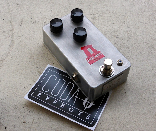
Here is my version:
Pharaoh Big Muff clone
As you can see, the Pharaoh has more controls than a classical Big Muff. There are the classic gain / volume / tone controls, like a classical Big Muff, plus a few other options. Here is the original version of the Pharaoh:
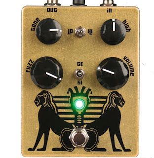
Black Arts Toneworks Pharaoh Fuzz
There are a "high" potentiometer that allows us to set the amount of trebles, and two switches. The first switch is a 'high / low' switch, that allow us to have 2 types of gain settings for the pedal: low gain and high gain. It modulates also a bit the trebles. Finally, you can choose the type of diodes in the last distorsion stage with the second switch: classic silicon diodes, no diodes or germanium diodes!
Black Arts Toneworks Pharaoh Fuzz clone
Finally, there are some modifications on the circuit. For instance, input and output capacitors are 10uF tantalum capacitors, which will let a looooot of bass go through the circuit!

Here is a gutshot (yes, I had fun drawing this!):
 Black Arts Toneworks Pharaoh Fuzz clone
You can see the tantalum capacitors that are drop-shaped. I try to avoid as much as possible to use it in my guitar pedals. They are not especially good for audio, expensive, and most of all there are not really "ethical friendly". Tantalum is produced from coltan, a mineral that is the root cause of many conflicts, especially in Congo. Illegal mines were opened without any regulation, degrading environment in an uncontrolled way, with many Human right issues (a bit of reading about that on wikipedia). Traceability is a big problem with electronics. Most of the time we do not know how, where or in what ecological context components are made... For tantalum capacitors, just know that they are easily replaceable by electrolytic capacitors.

Wima capacitors are much better for that: they are made in Germany (and thus, their production must respect European ecological laws and regulations). This is why I try to use them as much as possible:
 Pharaoh Fuzz clone
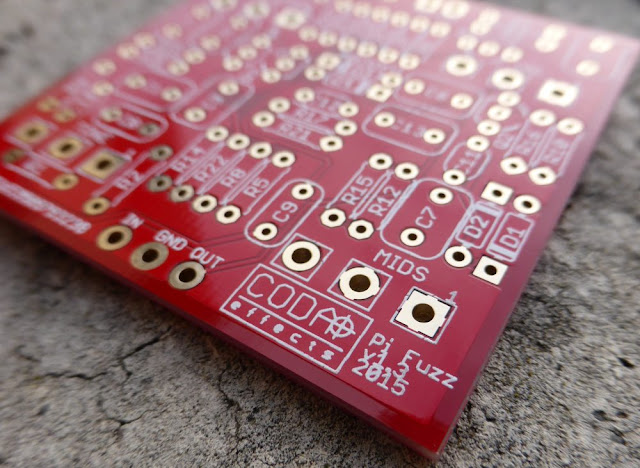
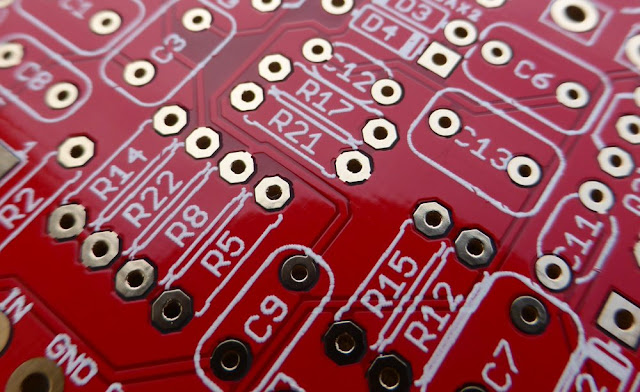
So, how can we make the Pharaoh from a classical Big Muff PCB?

Here is the schematic from the Big Muff page:
Pharaoh Fuzz schematic
As you can see, it is very similar to the Big Muff circuit! We can use the Coda Effects PCB and modify it following the above schematic. Here are the modifications to do:
- no mid knob, 470k for R5.
- no R2 resistor (we will use a switch instead)
- no D1/D2 diodes (switch here too)
- no R8 resistor. (replaced by a "high" potentiometer)
No big changes!

If you want, Rullywow sells a PCB especially conceived to make the Pharaoh Fuzz, named "King Tut". If these mods seems a bit difficult to do, you can buy this PCB to make it easier ! Rullywow creates really nice PCB, and this one is no exception, and is of very nice quality.

First, we will remove the mid knob by placing jumpers on the mid knob pads, like indicated on the build document.

To include the switches, we will have to use a 125B enclosure, it will not fit in a 1590B. We will have to use long lugs potentiometers to place switches so they do not touch the circuit board and create false contacts.

For R2 and D1/D2, we will use switches:
- SPDT on-on for choosing R2
- SPDT on-off-on to choose D1/D2 diodes.


Choosing R2: switching between the Hi/Lo setting of the Pharaoh

We use a "on-on" SPST. Signal arrives to the center of the switch, and goes through a resistor, 39k ("high" setting), or 390k ("low" setting):
Pharaoh mod
Try to make the connections on the other side of the PCB, it will be simpler. With this switch, you can choose the R2 value! In "high" position, there will be a lot of gain and trebles, whereas in "low" position, the sound will have more bass, less trebles.

It can apply to any resistor in the circuit, so feel free to experiment! Of course, some resistors are more interesting than others... I let you try!


Diodes choosing: 3 positions switch

We will use the same system for the diode switch. We are going to use a 3 positions on-off-on SPDT switch in order to have: germanium diodes (3 to have assymetric clipping), no diodes or classic silicium diodes. The second set of diodes to replace is D1/D2:
There it is! We have our two switches. Beware of false contacts with these switches: try to reduce the length of naked cables.Voilà ! On a déjà nos deux switchs !


Treble potentiometer

Last mod to add to have exactly a circuit like the original design: the treble potentiometer. In fact, you just have to replace R8 (tonestack resistor) by a 25k potentiometer. Just connect the lug 1 and 2 to each pad of the R8 resistor:
Pharaoh mod
It can also apply to any resistor! You can investigate to find your favorite resistor to modulate ;)
There it is! Voilà! We have got our Pharaoh Fuzz PCB!

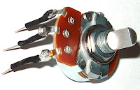
You can solder the other potentiometers now.  Beware: if we use "classic PCB-mount" potentiometer, the switches will not fit in the enclosure (they will touch the PCB and create false contacts). We will have to use "long lug" potentiometers like this ones:
long lugs potentiometer
You can also use classic potentiometer and make the lugs longer with soldered wire with solid copper wire or cur resistors / diodes lugs for instance.
long lugs potentiometer solder

You can now drill the 125B enclosure, and rock! :)
Have fun!

To go further:
Official Pharaoh webpage : if you are interested in buying the original pedal
Veroboard version of the pharaoh: a bit annoying and complex to make, but doable!
King Tut PCB: dedicated PCB conceived by Rullywow

Relay Bypass: conception and relay bypass code

You might already have heard about "relay bypass", or even used it without knowing it. It a different true-bypass system than the classical 3PDT switch. Instead of using a mechanical 3PDT switch, a soft switch, a microcontroller and a relay are combined to turn the effect on and off.

Relay bypass PCB DIY

 So... Why bother? My 3PDT switch is great, don't you think?

As you may already know, 3PDT switches are the main cause of guitar pedal failure. These switches are not particulary though, and they often break, especially as we smash it continuously with our feet on stage.

A classical high quality 3PDT switch is rated for 30,000 activation cycles. With relay bypass, we use a relay that will play the mechanical role of connecting ins and outs. Relays are usually rated between 10 and 100 millions cycles! Thus, this system is much more reliable.

Moreover, the soft switch that we use to activate the guitar pedals also last longer than a 3PDT, usually around 50,000 cycles! They are also easier to replace, as there are only 2 connections to make with the relay bypass system, and not the full 3PDT wiring.

This blog post will present you how does it work, and how to make your own relay bypass system using a microcontroller, from the beginning to the end! Long stuff (but good stuff?)!

Guitar effects and reliability: 5 things to improve to make your pedals longer lasting

I am building effects since three years, and now that it has been a while, I noticed first failures on my devices. In this article I am going to describe what are the main causes of guitar effects failures that I noticed or that people report to me, how to repair it, and how to build your pedal to make them long term lasting or easily repairable.
Oxydated chip guitar pedal


1. 3PDT switches

3PDT switches are the main reason why a pedal stops working. A broken 3PDT switch can cut your sound, and the pedal is not easy to switch on and off. 3PDT (and switches in general) are mechanical devices that suffer when activated a lot of times. Usually, good quality switches are rated for 30 000 cycles, but with the way we treat our pedal (kicking them all the time on stage), they usually fail sooner than that. Moreover, most of the times, we do not use good quality switches, but rather “China Blue” 3PDT that are not that reliable (but way much cheaper than Alpha switches).

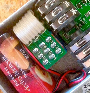
Replacing a switch is easy but sometimes quite annoying, as you have to rewire everything. To make replacement easier, you can use 3PDT miniboards and ribbon cables. This system is used in many commercial pedals, like in Electro Harmonix or even Diamond pedals:
3PDT board electro harmonix PCB

But what if you just want something more reliable? Another solution is to use relays instead of 3PDT as a mechanical system to switch the signal. A normally open momentary soft switch can be used with a microcontroller to drive a relay to switch the signal. Indeed, relays are rated for way more cycles than mechanical 3PDT. For instance a Panasonic TQ2-L 5V, which is a classical relay is rated to last between 10 and 100 million cycles! The momentary switch is really easier to replace than the 3PDT switch, only 2 cables to solder. Here is an example from the Dr Scientist Bitquest pedal (great brand!):
 Relay Bypass guitar pedal
I am planning on using this kind of system on my pedals soon. I have written a code for a PIC 12F675 microcontroller to use this kind of system. I am now designing a PCB to use it as a standard activation system, with some tricks. Also, this switching scheme is totally silent, which is nice!


2. Wiring dessoldering

When wiring the pedal, cables are not always really fixed, and the solder can break and cause a disconnection in your wiring. This can happen quite easily on the 3PDT jack where there is a lot of wiring going on, or even on input jacks. It can make the pedal mute, or generate a huge amount of noise if there are grounding issues arising from a dessoldered wire. It is easy to fix (just ressolder the wire), but quite annoying if the person cannot fix it at home (no soldering iron…etc) and needs to send the pedal over. There are two ways to prevent that. The cheap way to do it is to apply a kind of glue on the soldered wires to avoid physical stresses that cause unsoldering. This is the case in this Caline pedal (Chinese cheap clones):

Caline Reverb PCB inside
But the best way to prevent it is to include the wiring directly on the PCB, ie include the jacks and 3PDT on the PCB. It is possible to use a separate PCB for the true bypass wiring like in this JHS pedal:
JHS True bypass PCB
Or you can include the switching scheme directly on the PCB. I am planning on including it directly on the PCB on the new pedals I am prototyping. It also makes assembling easier and faster.


3. Loose jacks and 3PDT

This is a classical problem. Input jacks and the 3PDT can sometimes become a bit loose, even if you tight them with a pair of pliers. In the worst case scenario, the nut or the bolt can be lost in the process, and the pedal would be quite difficult to use if the input jack or the 3PDT “enters” inside the enclosure… It is really easy to fix, but it is a very common problem, and quite boring to repair because the customer would have to send it over (or I would have to send screws to repair it) just to fix a loose jack. There are two ways to avoid this: either your tight it a lot with a pair of pliers, either you can include jacks directly on the PCB.

However, it has one downside: if the jack input is not working anymore, it is quite boring to replace because dessoldering and ressoldering of the jack is not easy. So, do not forget to use high quality jacks like Neutrik NMJ6HCD2, and not to overcrowd the PCB around the jacks to make dessoldering possible.

I am designing my first “commercial” pedal, and I plan to include the jacks directly on the PCB. It avoids a lot of wiring (reason 2), and prevents loose jacks.


4. False contacts

If you let your PCB “free” in the enclosure, or just wire it without solid core wire (bendable wire), the circuit board can move in the enclosure. Sometimes, it can create false contacts that are quite boring to fix because you never know where it comes from. Also, it happens a lot with veroboard, where the copper side can make false contact with the bottom of the enclosure. The classical "spaghetti wiring" of beginners is also quite dangerous for that...

Guitar pedal spaghetti wiring
My recommendation would be to use PCB mounted potentiometers, which make the PCB fixed in the enclosure. If you are using a veroboard, use solid core wire to make the wiring, so you can bend it and try to fix the veroboard in the enclosure. But my ultimate recommendation would be: do not use veroboard. Honestly, it increases the risk of mistakes (misplacing components on the boards, complex wiring…), and can create false contacts easily. A PCB does not cause all this problems and is much more reliable in terms of assembling. This is why I use mostly PCB in my pedals now.


5. Component failure

Actually, I have never seen a component failure per se. Most of the failure I observed resulted from a power supply mistake. The most common case is with MAX1044 (voltage inverter / voltage doubler IC), that can only accept 10V maximum. If someone tries to apply an 18V voltage for instance, the chip simply stops working. Another thing that happens is when someone uses an inverted voltage on a pedal using a normal voltage (polarity inversion). Usually, the diode that protects the pedal from it usually just burn / melt and has to be replaced. Here is an example of a melted diode:
Burnt diode guitar pedal

For the MAX1044, I use a socket so it can easily be replaced. For the diodes, I use a “long legs” package on my PCB so I can just cut the legs of it, which makes dessoldering easier. Also, SMD components are much more difficult to replace, so I would advise to avoid it.


There it is! This are the 5 main points I noticed concerning guitar pedal failure. I am sure that you can spot other things that make your pedal fail, do not hesitate to tell me by posting a comment!
If you like this article, thank me by liking the Coda Effects facebook page, or by subscribing to the newsletter!

Dead Astronaut FX Chasm Reverb

Remember my Dead Astronaut Chasm Reverb PCB? I finally finished it! I left it quite a long time aside my bench, mainly because I did not have time or money to buy and build all the remaining things that needed to be done. Remember, if you want to have one, you can buy one directly from Dead Astronaut, or buy the PCB to make it yourself.

Here is my build: 
Chasm Reverb Prismatic dead astronaut
I used a prepainted enclosure, with a nice vintage color vibe, close to Surf Green color. With cream knobs of course! I just miss a cream pickguard part to have to most vintage fender look!

As I already said before, it was a fun build to make. The PCB is quite big and components are well spaced, so it is really easy and fun to build it, even for a beginner. I had absolutely no trouble at all. I did a few mistakes with the wiring, which is not a common wiring scheme as the pedal is buffered bypass. Apart from these minor incidents, the pedal almost worked immediatly, nice!
Chasm Reverb Prismatic dead astronaut

There are four potentiometers: volume (to set the output volume), mix (allows you to mix the dry signal with the reverb signal, you can go from a 100% dry to a 100% wet signal), damp (set the overall brightness of the reverb) and decay (set the amount of reverb that goes to into a feedback loop). Indeed, one of the features that make this reverb unique compared to other Belton Bricks reverb out there is that a part of the reverb signal can go through a feedback loop, allowing the reverb to auto oscillate! The switch allows to put the reverb in auto oscillation mode.


How does it sound?

I finally invested in proper recording gear (Senheiser e906 and external audio card), so I manage to record something for you! The Chasm Reverb is a deep, spacy sounding reverb, very good sounding with a delay!

The volume potentiometer is useful if you make it oscillate. At max, it is normal volume level, and you can lower it. The Mix is also quite useful, although I do not really like a too wet sound. The oscillation switch is really killer.

You can make the reverb smoother, and create "waves" of sounds, that lush for a quasi illimited amount of time! It is really awesome when combined with a delay! Perfect for ambiant stuff, and you can leave it on on the background.


Circuit analysis

Here is the circuit, from the build document:
Dead Astronaut Chasm Reverb Schematic
If you have already read the circuit analysis of the Rub A Dub Reverb, you can already find some similarities. As most of the DIY reverbs, it uses a Belton Brick, an IC that allows DIYers to make reverbs without having to use a spring reverb tank.

It is divided in several parts:
Dead Astronaut Chasm Reverb Schematic
Let's analyze each part of the circuit.


Power supply

The power supply is a classic one that we can find in many circuits. It provides 3 different regulated tensions:  9V, 4.5V and a regulated 5V.
Dead Astronaut Chasm Reverb Power Supply
The Zener diode (D6) prevents polarity inversions. R22 and C16 forms a low pass filter that will eliminate any 50Hz parasitic voltage ripples remaining from your AC outlet.

R23 and R24 forms a voltage divider that provides a 4.5V tension (VB). It is regulated by C17, a 47uF capacitor that will absorb excess of voltage. This tension is necessary for the OP amps to operate correctly

Then, there is a voltage regulator, REG1, that is a 7805. "78" means that the output tension is positive, and "05" is the output tension, 5V. The regulator is necessary to supply the Belton brick a good voltage. Unregulated voltage could result in damaging the IC that is very sensitive to higher or lower voltage drops, and so requires a regulated tension provided by this small chip that look like a transistor! You will find this kind of regulators in almost every circuit using numeric IC.


JFET switching buffer

This is a peculiar switching schematic that is very pratical here because it allows the use of a buffered bypass setting that make reverb trails possible. In a true bypass setting, the reverb would be cut abruptly when the effect is turned off, whereas here it can slowly decrease
JFET switching schematic circuit
So how does it work?

First, there is an input buffer, formed with R1, C1, R2 and the first OP amp of a TL072. As you can see, there is no resistor in the loop of the OP amp, thus it has a gain of 1. It is just used to transform the low impedance signal from the guitar into a low impedance signal.

Then, ther is the proper JFET switching. Here, JFET transistors are not used like amplifiers, but rather like "on / off" switches (like in computers!). When the JFET is turned on (by supplying 9V through the DPDT switch), it allows the signal to go from the drain to the source: the signal can pass. When a JFET is on, the other is turned off, so the signal either goes to the effect, or to the buffered output. A diode prevent any parasitic signal from the gate to enter in the signal path.

This switching scheme is nice with a reverb: it diminishes "popping" issues, and allows reverb trails, which is super nice with this reverb and its auto oscillating feature.


The Reverb circuit

The reverb circuit uses the Accutronics reverb module, a great integrated circuit that I presented already in the Rub A Dub Reverb circuit analysis.
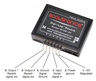
Here is a schematic of the BTDR-2H that is used in this circuit:
Accutronics BTDR 2H Belton Brick
There are 6 pins on the brick. The two first ones are used for the power supply. Note that the power ground is supposed to be different than the signal ground. In some circuits, that is very important to separate digital and analog ground, and to combine them in only one point in order to diminish noise (especially if you combine digital chips with analog ones like MN3005 that are also in 5V).

The guitar signal enters in the third pin (signal ground on the 4th pin), and is "transformed" by the chip in a reverberated sound that goes out at the 5th and 6th pin. The reverbarated sound is not the dry sound + reverb sound. It is just the reverberated sound, so it is kind of peculiar. You have to mix it with the dry signal to make it sound like a reverb.

Here is the schematic of the reverb:
Dead Astronaut Chasm Reverb schematic

So first, there is a MOSFET input buffer, that increase a bit the signal. The signal is then split in two. A part of it stay dry (Dry signal part), and the other is treated by the Belton brick (reverb signal), they are mixed in the end with a mix potentiometer so you can set the amount of dry signal versus the amount of reverberated signal.

The dry signal just goes through this section without being modified, and goes to the mix knob.

The reverberated signal is buffered by an OP amp (TL072), with a gain of one (so no gain basically). A 100pF capacitors in the loop rolls off a bit of highs, and the signal can enter the BTDR2H brick. The signal then goes out from pin 5 and 6 of the reverb. The high are roll off by a low pass filter formed by the "DAMP" potentiometer and C5. For more infos about low pass filters, read my post about the Big Muff tonestack. Thus, you can set the amount of trebles in the reverbarated sound. Then, the reverbarated sound goes through an OP amp in a similar layout than at the entry. The signal then goes to the mix knob.

If that were the only features of the Chasm Reverb, this reverb would be a simple reverb with a tone control. What makes this reverb unique is its feedback loop. A part of the reverberated signal can go in the feedback loop and goes back to the entry of the reverberation circuit. The amound of signal going back to the begining of the circuit is set by the Decay knob and the switch that let you choose between a 47k resistor (a lot of signal goes back: oscillation) and a 100k one (less signal goes back: more a long-decay like reverb). This is really cool because if you set a high decay, a lot of signal can go back in the reverb circuit, and it can actually autooscillate! It also allows to approximately set the decay of the reverb, which is not possible with a standard BTDR2 brick.

After the dry and reverberated signal are mixed with the "mix" knob, there is another knob, that acts as a master volume knob. It is wired as variable resistor, and acts as a classic volume knob. The signal (reverb + dry) can now goes through the output buffer.


Output buffer

The output buffer is a simple buffer using a single OP amp from a TL072 chip.
Dead Astronaut Chasm Reverb schematic buffer
A 100pF in the loop rolls of a bit of highs. If the pedal is off, the dry signal goes through it with a gain of 1 (resistor R16/R13), but if the pedal is on, it has a bit of gain (R15/R16) to compensate the loss of volume due to the Belton Brick, the mix and volume knobs. It is a simple buffer, very transparent because of the high values of the coupling caps (C10 and C13, 10uF) and the use of the TL072.

There it is! I hope that it is clear and that it was helpful! Do not hesitate to ask questions in the comment. If you like this post, thank me by liking Coda Effects Facebook page!


To go further

JFET switching (pdf by Geofex): great explanations about JFET switching, around the classic Boss / Ibanez circuit.
Accutronics BTDR2 official webpage. 
Pedalrig tips about noise, great infos too!
Chasm Reverb official webpage, if you want to buy a built one or a PCB!

ProCo RAT White Face (1985)

Here is a pedal a customer sent me for repair: a vintage ProCo Rat from 1985! This 30 year old little monster had some troubles with switching, happens that the switch that had been changed made some false contact with the (rusty but still conductive) metallic enclosure. 

It is a classic RAT2, produced in 1985. It is called "White Face" RAT because of the white background of the "RAT" logo. Later versions have a dark background with white lettering.
ProCo RAT white face 1985
The RAT is one of the first distorsions ever made. It was created in the late 70s by Scott Burnham. He was a tech working at ProCo, a super small sized company in Kalamazoo. He was working in his basement, with the rats, hence the name of the pedal!

The RAT has been declined in several versions. The first version, "The Rat", was handmade in Kalamazoo, in a small production manner (like you and me making DIY pedals!). The demand rapidly increased, and the production was switched to an industrial process. "The Rat" was produced from 1979 to 1983. In 1983, the enclosure was changed to a smaller sized one, and the ProCo RAT2 was issued. It is this one!
ProCo RAT white face 1985
It has three controls: distorsion, volume and filter. The filter knob acts as a reverse tone knob. The more you drive it to the right, the less trebles you will have. Input and output are on the top of the pedal (top mounted jacks is the best!). The DC jack input is an old style one, not really useful today where most of the power supplies uses 2,1mm Boss-style jacks.

Since its realease, the RAT pedal has been used extensively by many guitarists. Among the most famous are Kurt Cobain (Nirvana), Jeff Beck, Radiohead et Sonic Youth guitarists or Graham Coxon (Blur). You can see that it has been used a lot in the indie scene. It is an agressive distortion sound, full of harmonics that suits very well grunge music for instance!
ProCo RAT white face 1985
The RAT is still in production, with a red LED in the "RAT" logo. It has been declined in several versions. The original RAT uses standard 1n914 silicon diodes, whereas the turbo RAT uses LED for the clipping. Finally, the "you dirty RAT" latest version of the RAT uses 1n34A germanium diodes... You can use a rotary switch to have all the versions in one pedal!

ProCo RAT white face 1985 
Inside this black box, we can find the classic Motorola LM308 chip, that is now quite difficult to find, and quite expensive too! It is a simple double OP-amp, which provides some of the unique characteristics of the RAT pedal. Today, RAT pedals features a different chip, the OP07DP from Texas Instruments.
ProCo RAT white face LM308N IC
The vintage RAT was reissued with the LM308 chip. In 2010, ProCO even reissued this precise 1985 white face RAT!

Here is a great schematic that sums up all the differences between the different versions of the RAT pedal (click on the image to read it better):
ProCo RAT versions schematic
I hope to release a video soon to show you the sound of this vintage RAT!

To go further
History of RAT pedals (official RAT website)
Scott Burnham interview in 2012 (New York Time magazine)
Circuit analysis by Electrosmash: excellent! Really detailled analysis of the circuit and its variations.
History of RAT pedals: pictures of all the models of the RAT pedal. (here is the RAT2 page)
Manual of the RAT2 (pdf)

Big Muff PCB available!

The Big Muff PCB that I conceived finally arrived in its final version... And it is alive! I also wrote a detailed build document.

Big Muff PCB 

It is a double layer PCB to make your own Big Muff! I added a fourth optional knob: the mids knob. Mids are a huge turn off for me with Big Muff: all your medium frequencies are scooped! 

When you use one in a band, you always disappear in the mix, quite boring when you want to use the loudness and sustain of a Muff and be heard! I made it optional in case you want to stick to the original design. Thus, you can make any Big Muff variant that you want, including "boutique" variants that often use a mids knob!

EHX Big Muff Russian PCB

I made it usable for a 1590B, so quite a small enclosure compared to the original Big Muff, ideal for crowded pedalboard purposes! But you can use it in a bigger enclosure, allowing a lot of mods.

Ready to make your own Big Muff? Get one here:

 Buy


The quality is maximum with this PCB: it has been made using an immersion gold process that ensure easy soldering, and long lasting connexions. The PCB is lead free, so it can be used in any country (Europe does not allows lead in solder or electronic devices). Pads are quite spaced, and are big enough to allow easy soldering.

Big Muff circuit board

I used he same components name than in The Big Muff page. This is very useful, you can just pick the version you like on the Big Muff page, and make it yourself quickly! It also makes mods easier to do, and you can relate quickly between the excellent circuit guide from the Big Muff page to the PCB.

Electro harmonix Big Muff circuit board PCB

Example of a pedal made with the PCB

Here is a Ram's Head I made with the PCB. It is made wit a "replica" spirit: I used the exact same values as a 73' ram's head. I always wanted to know exactly what it sounded like, so this was a good time to try it!

Big Muff Ram's Head DIY

This pedal was made to test the "optionality" of the mid knob, really easy to do. I used my "Dolmen Fuzz" logo, made by HPM laser. I used a standard 1590B Hammond enclosure, that I polished with sand paper like my other Big Muff.

Big Muff Ram's Head DIY

As you can see, it fits perfectly in the enclosure. I tested my drill template, it is perfect! As you can see, I made the wiring easy:

Big Muff Ram's Head DIY

I also tested the compatibility of the PCB with Wima MKP2, which are really good capacitor for audio. Works well and gives a niche red touch to the circuit!

Big Muff Ram's Head DIY circuit

With my PCB and the detailed build doc I have written, you should be able to make your own Big Muff easily!

Ready to build yours? Get one here:

 Buy