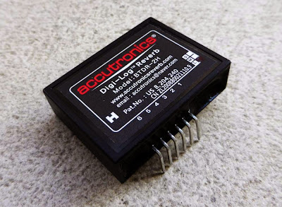
This brick contains a rather complicated circuit with 3 PT2399 (numeric delay chip) that follow each other with really short delay time to act as a reverb.
Bam! I told you it was kinda complex...
They
managed to make it smaller as possible with surface mounted components
so we, small DIYers can use it at home to make our reverbs!
It has 6 pins:
- Pin 1 should receive a regulated +5V voltage
- Pin 2 should be connected to power ground
- Pin 3 is the input of the circuit
- Pin 4 is the signal ground
- Pin 5 is the output 1
- Pin 6 is the output 2 (for stereo applications)
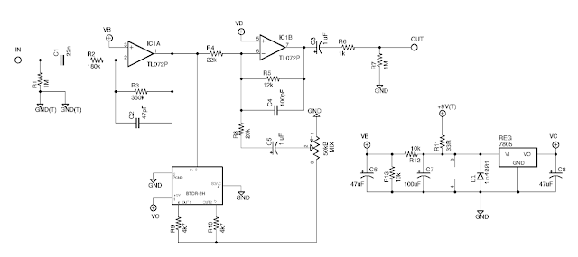
The Rub a Dub reverb is a circuit surrounding this belton brick in order to get the most of it with a simple layout. Here is the schematic:

Let's divide it in three sections:

The
input buffer is a simple OP amp boosting the signal before it is split
between dry (analogue signal) and wet (numeric conversion and treatment
by the Belton brick). First, there is a 1M pulldown resistor that
prevents "pop" noises when a charge accumulates at the entry of the
circuit. The excess of current is going to the ground when the effect is
activated. Then, there is a coupling capacitor (22nF), preventing any
parasitic direct current to go in the circuit. The signal then goes
through a resistor and the first OP-amp of the TL072. The TL072 is an IC
containing 2 OP amps, which is a low noise JFET amplifier. It is wired
as an inverting amplifier. Thus, we can calculate the gain of it, which
is simply R3/R2 = 360/180 = 2. The OP amp multiply the signal by 2, so
when it is split between the dry and wet section, it is like having 2
signals like the original one going on each side of the circuit.
The treated signal section (wet section) simply is the Belton brick circuit. The signal enters through pin 3 and goes out through pin 5 and 6. It is then mixed with two 4,7k resistors accordingly to Belton mono circuit example.
The signal that goes out the brick is the reverb signal ("wet"
signal). The signal then goes back to the amplification loop of the
second OP amp. First, the "mix" potentiometer sets how much wet signal
is going back in the circuit to be mixed with the dry signal. So you
define how much signal there will be in the final sound! A coupling
capacitor prevents any parasitic DC current to go in the circuit, and a
20k resistors defines how much signal can go through at the minimum mix
level. A fun mod to do is to put a switch before the 22k resistor in order to make the entire signal going through the wet section: all the signal will be treated, and you will not have a dry signal anymore, creating a "wet" reverb.
The mixing section mixes the dry signal with the wet signal using the second OP amp of the TL072. The
amplification gain is around 0,5, so that the mixed signal will be of
the same amplitude that the original input signal. Thus, the volume will
stay constant. By modulating the resistors values, for instance the 12k resistor, volume can be increased or decreased.
It is also possible to put a potentiometer there in order to have a
volume / boost knob. Then the signal goes through a 1uF coupling
capacitor, and there is another pulldown resistor to prevent noises, and
it finally gets out!
The power supply section stabilizes the current and offers a 4,5V voltage, and a regulated +5V voltage.
This is important to supply the voltage needed by the TL072 and the
Belton Brick. The current enters via +9V(T), goes through a 33R
resistor. A 1n4001 diode protects the circuit against polarity
inversion, and a 100 uF capacitor eliminates all
the residual oscillations that may come from the power supply. More
details about the stabilization of the power supply in my dedicated article.
On the left side of the power supply section, there are 2 resistors
that act as a voltage divider. Half of the current goes through the 10k
resistor linked to the ground, and half of it goes to VB. We have a 4,5V
VB voltage, perfect for the TL072! On the right of the circuit, there
is a 7805 REG regulator. Even if it looks like a transistor (with 3
pins), it is an integrated circuit with a simple role: a voltage between
7 and 36V can enter through pin1, and a stable 5V voltage goes through
pin3. Pin2 is connected to ground. It is really convenient when you need
a stable particular voltage. There are many possible versions for
voltage regulators, depending on which voltage you need:
- 78xx: positive voltage
- 79xx: negative voltage
- "xx": voltage value of the regulated voltage output.
Any questions? Post a comment!
To go further:
Belton brick BTDR2H official webpage and datasheet.
Rub a Dub reverb bill of material and informations
About 7805 voltage regulator: more infos here.

5 Comment
hi there! i really liked your post!
Answeri was just wondering if i could make a bdtr2 daughterboard with that schem you provided just for fun...
but i have some questions.can you tell what's that part of the circuit at the bottom left? the one with the 3M3 and the 50p?other than that, i believe i can draw a layout to see if that works
thanks
Savvas
It's a simple CMOS oscillator. The triangle represents a Schmitt Inverter. You'll find six of these inside a 40106 or a 4584.
AnswerIt wouldn't let me access the
AnswerBelton schematics thru that link. Says I don't have permission and keeps telling me to sign in with a password. But otherwise this was an excellent article. Twelve thumbs up it!!
Who can pick out for me the best product from the list provided in this site?
Answerhttps://latestmusicalinstrument.com/best-computer-for-music-production/
Who can recommend to me the best product among those in the list on this site?
Answerhttps://latestmusicalinstrument.com/best-acoustic-electric-guitar