Here is a first build I made not so long ago, an Analogman Sunface.
Very simple layout, a classic fuzz face with some light modifications, like a bias pot that I called "woof" here for fun.
Since this first picture, I improved a bit the circuit with transistors sockets that are very nice in order not to overheat germanium transistors, and to test different combinations of hfe.
You can see the really simple NOS components here: carbon comp resistors, Mullard "tropical fish" capacitors (love this name, very accurate description!) and of course two AC128 germanium transistors.
I got most of these compounds in old radios that I disassembled a long time ago, except for the germanium transistors that I bought online. I used the guitar fx layouts scheme to do it and I enlarged a bit because my capacitors were axial. Since, I built another fuzz face using a PCB.

If you want to be super accurate, "vintage correct" or full mojo for your build, then you should get the original components (even if - apart from the transistors - I do not think that it will change the sound a lot):
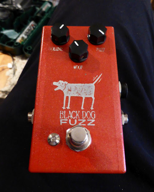
 I reverse-etched the enclosure, which was quite of a job, but I love how it finally came out! If I do another one, I will maybe readjust a bit the position of the main logo.
Germanium transistors gives the fuzz a nice smooth saturation, still a bit mushy/harsh, but not as gritty as other silicon fuzz like Big Muff for instance.
Fuzz face is really a simple circuit design, as you can already tell by the number of components of the circuit: 4 resistors, 3 capacitors and 2 transistors! And of course two controls: fuzz + volume! As simple as that! But when we look at the circuit:


References / to go further:
http://www.geofex.com/article_folders/fuzzface/fffram.htm
http://fuzzcentral.ssguitar.com/fuzzface.php
http://www.electrosmash.com/fuzz-face
http://www.analogman.com/fuzzface.htm
Very simple layout, a classic fuzz face with some light modifications, like a bias pot that I called "woof" here for fun.
Since this first picture, I improved a bit the circuit with transistors sockets that are very nice in order not to overheat germanium transistors, and to test different combinations of hfe.
You can see the really simple NOS components here: carbon comp resistors, Mullard "tropical fish" capacitors (love this name, very accurate description!) and of course two AC128 germanium transistors.
I got most of these compounds in old radios that I disassembled a long time ago, except for the germanium transistors that I bought online. I used the guitar fx layouts scheme to do it and I enlarged a bit because my capacitors were axial. Since, I built another fuzz face using a PCB.
If you want to be super accurate, "vintage correct" or full mojo for your build, then you should get the original components (even if - apart from the transistors - I do not think that it will change the sound a lot):
- NOS vintage NKT 275 Germanium Transistors
- NOS vintage Mullard Yellow Capacitor
- NOS vintage Philips Capacitors
- NOS vintage Allen Bradley Resistors
How does it sound?
I made a few samples with my Gibson Les Paul 1954 reissue (gorgeous guitar, the best!), on a Vox Lil' Night Train, a small practicing tube amp that I use at home.Germanium transistors gives the fuzz a nice smooth saturation, still a bit mushy/harsh, but not as gritty as other silicon fuzz like Big Muff for instance.
How does it work?
Fuzz face is really a simple circuit design, as you can already tell by the number of components of the circuit: 4 resistors, 3 capacitors and 2 transistors! And of course two controls: fuzz + volume! As simple as that! But when we look at the circuit:
Fig.1 Fuzz face circuit, classic 60s original schematics
(made with Fritzing)
Not so easy to understand, isn't it?
Let divide this schematic in 3 sections:
Fig.2 Fuzz face circuit, classic 60s original schematics
with different sections of the circuit
(made with Fritzing)
The first capacitor (C2, 2.2uF) filters the DC current at the entry of the circuit to avoid troubles with the next part of the circuit. This kind of capacitor (that you will find in a lot of circuits) is called a coupling capacitor. It also acts as a high pass filter, removing some bass frequencies. Enlarging its value will let more bass go through the circuit.
The gain amplifier section (blue part of the circuit) is a simple common emitter layout to amplify the signal. It has the maximal gain possible in this configuration: the emitter is directly connected to the mass, and the collector is directly linked to the base of the second transistor. It is a very classical layout that you will find in many many transistor based circuits, even if usually a resistor is present between the emitter of the transistor and the mass. This stabilizes the circuit, and allows a fine tuning of the transistor gain by creating a negative feedback. The second transistor is in the same layout, except for its emitter.
The main interest of the circuit is the feedback loop (in green). The emitter of the second transistor is linked directly to the base of the first one through a 100k resistor. A part of the current goes back to the first transistor, creating an amplification loop: current from Q2 comes back to Q1!
The counter reaction (therefore the gain) of the second transistor is modified by a variable resistor placed between the emitter of the transistor and the mass: the fuzz potentiometer! By diminishing its value, the quantity of current going to the mass increases whereas the amount of current going through the feedback loop is diminishing. If the value of the variable resistor increase, more current goes through the feedback loop: the base of Q1 receives more current, saturation increases.
The volume / output section (in red) is the simplest volume control that you can imagine: a 0.1uF coupling capacitor to eliminate DC current, and a volume potentiometer wired as a variable resistor. The output signal will be more or less important depending on the value assigned to the potentiometer.
Fig.3 Analog.man Sunface circuit
(made with Fritzing)
The Analog.man version of this circuit introduces some little improvements to this circuit. First of all, a trimpot (wired as a variable resistor) is present at the input of the circuit before the 2.2uF capacitor. Thus, the entry impedance can be adjusted a bit. It plays the same role as a guitar volume pot, so you can adjust the fuzz gain, which is really useful for high output pickups for instance.
Another modification to the circuit is the 8.2k resistor that is replaced with a 2.2k resistor plus a 5k linear potentiometer. I prefer to use a 10k potentiometer so the original 8.2k value is reachable. This modification allows you to set the bias of the second resistor. It is useful in order to have the maximal gain, especially as the circuit is really temperature-sensitive.
Finally, some values are changed compared to the original circuit: the coupling capacitor is 1uF and the one before the volume pot is 0,01uF. The volume potentiometer is 250k. All together, this will remove a bit of low end, making it a brighter fuzz. This is probably done in order to compensate the deeper tone of the NKT275.
Nothing difficult, but still good improvements to the circuit !
How to make it?
Even if the circuit is really simple, there are some recommendations to follow in order not to mess with it:- Beware of the orientation of the 10 and 22 uF capacitors: electrolytic capacitors are polarized. Messing with the orientation can result (in the best case) in a non-working circuit, or in the explosion of the capacitor, which really not a nice thing to happen !
- The transistors are the main part of the circuit, and there are some precautions to take with it. Verify that the orientation (Collector, Base, Emitter) is correct before plugging the DC power.
Fig. 3 Collector, Base and Emitter of germanium transistors
(C, B and E, respectively)
- Do not overheat germanium transistors! These pieces are very fragile, sometimes a bit of solder can kill them... Additionally, germanium transistors are most of the time quite expensive devices, so I would really recommend to use a solderless method like transistors sockets, and to wait that everything is really cool before putting them in. So, of course, the couple of transistor is the last component to be added to the circuit.
- Last but not least: the circuit needs a negative tension to work properly (-9V). Do not try to use your good old boss charger!
References / to go further:
http://www.geofex.com/article_folders/fuzzface/fffram.htm
http://fuzzcentral.ssguitar.com/fuzzface.php
http://www.electrosmash.com/fuzz-face
http://www.analogman.com/fuzzface.htm