Showing posts with label Step by step. Show all posts

Tutoriel: how to prototype with a breadboard

Prototyping is not always an easy task with guitar pedals. One solution is to heavily mod an existing pedal. But what if you want to start from scratch? How to test things before designing a circuit and solder everything?

Well, we have a simple solution for that: using a breadboard!
DIY guitar effect breadboard

Let's go! In this blog post, we'll see why the breadboard is such a cool tool and how you can use it to design and test your own circuits.


How to build your first DIY guitar pedal (step by step tutorial)

You have never made a guitar pedal before? You are a bit lost and do not know where to start?

Here is the perfect place! I decided to write a full tutorial for beginners, to build an Earthquaker Device Acapulco Gold, step by step. No excuse not to get started!

The Acapulco Gold is a simple, yet very fun pedal to play with, and is perfect for beginners. The circuit is simple and easy to mod as well. With this tutorial, you should be able to build your first guitar pedal!

If everything goes well, you should get a guitar pedal like this in the end:

Acapulco Gold clone

Ready to make your first guitar pedal? Let's get started!

Modding the Behringer UV300 Vibrato : tutorial

Here is my last ""build", I modded a Behringer UV300 vibrato:
Modded Behringer UV300

Behringer released a whole series of pedals inspired by not-produced-anymore Boss pedals like the Hyper Fuzz FZ2 (Behringer Super Fuzz 300), the Heavy Metal HM2 (Behringer Heavy Metal 300)...etc. I was really interested in one of them: the Behringer Ultra Vibrato, which tries to emulate the famous Boss VB2.

Eagle for making guitar pedals PCB: getting started (part 1/3)

Sometimes, especially with complicated builds with a lot of components, or when you have to build several times the same pedal, it is easier to use a printed circuit board (PCB) than veroboard or turrets board. A PCB is easier to assemble, and it prevents from doing many mistakes that can occur when using veroboard: false contacts, misplaced component, complicated wiring involving a lot of wires...etc.

"Eagle" is the name of a beautiful animal, but it also stands for "Easily Applicable Graphical Layout Editor", the name of a famous software that helps you to conceive and make printed circuit boards (PCB). I already used it a lot to make PCBs. For instance, I made a few Klon buffer boards with it. I decided to write a serie of articles explaining how to use it to make PCB for your guitar pedals.

Article parts:
  • Getting started (you are reading this one now)
  • Tracing the circuit (to be published)
  •  Creating the PCB layout (to be published)

Eagle 
Become free to make PCB like you want with Eagle


Why using Eagle?

There are many different different software to create PCBs that are available nowadays: DipTrace, KiCad (open source), Express PCB, Fritzing... Why using Eagle instead of these ones?
Well, there are several reasons.

Eagle is free. If you are using Eagle for your personnal use, it is a freeware. Of course, there are limitations that come with the freeware version, but they are not really a problem when it comes to guitar pedal PCB development: maximum size of 100 x 80 mm (4 x 3.2 inches), which is really big for a guitar pedal PCB, only 2 layers maximum (well, we are not going to use more anyway), and one schematic maximum per project. If you want to sell your projects, you will have to buy it, but for simple projects like guitar pedals, the Lite edition is enough and costs only 69$! If you need to buy it, respect the developpers, do not be ill-eagle (badum tsss) and buy it.

Eagle is well documented. There are a lot of books, websites, videos that are dedicated to Eagle software. If you ever encounter a problem, or if you do not know how to use a precise function, you will always find a solution somewhere. I will write a list of useful websites down this post.

Eagle has the most complete libraries. When creating a PCB, you need to specify what component you are going to use in your circuit. Is it a small 1/8W resistor, a big 1W one?  Is it an electrolytic capacitor or a tantalum one? You can imagine that it is very important to precise it in order to have the good component "shape" on your PCB. In order to do that, you have lists of components that are called "libraries", which contains hundreds of different components! Eagle has a lot of libraries for all kinds of components, and some libraries had been made especially for guitar pedals!

Eagle is easy to use. Most PCB softwares are easy to use, and Eagle is too! The "graphical" word in "EaGle" simply means that you have a wysiwyg interface. The interface is easy to use, and let you directly move the components on the board. Last thing, it works on windows and mac, which is nice if you are using different operating systems.

Convinced? Let's get started!


Installing Eagle

Download Eagle on CadSoft website, and install it as a freeware (except if you are going to sell the PCBs you make with it)


The libraries

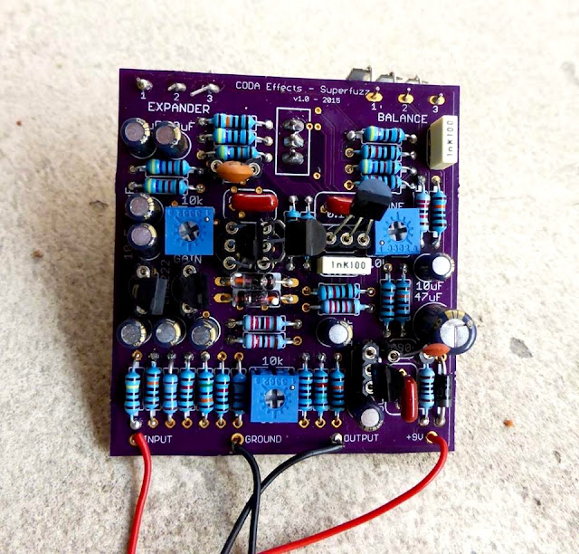
When you create a PCB, you need to be very precise about which component you are going to use. Indeed, if you put a wrong reference somewhere, the spaces between the lugs can be too short / too long, the component could be too big to fit the PCB...etc. For instance on this PCB:
Superfuzz PCB circuit board
You can see that every component fits perfectly its location on the PCB. This is because when conceiving the PCB, I used the correct references for each components.

A library is simply a list of components referencing components sizes, values and shapes. Eagle comes with already a lot of libraries pre-installed. Some of them will be really useful (Resistors, Capacitors, Inducors (RLC), transistors, supply...etc), some of them not (Zilog microprocessor devices?).

Some libraries had been created specially for guitar pedal PCB making:
Gauss Markov library: very easy to use library with a lot of useful components.
Madbean pedals library: Brian (owner of madbean pedals) made available libraries for making guitar pedal PCB.
I strongly suggest that you download these libraries. They are easy to use, and contains all the basic tools that you need for making guitar pedal PCBs.

To install a library, unzip the files, and copy the .lbr files in the "Eagle v7.2/lbr" folder. It is in the applications folder on mac, or in the program files folder on windows.

Then, open Eagle. You should have a window like this, which is the control pannel:
eagle control pannel
You can see that there is a "Libraries" folder that can be expended. It contains all the libraries that you have in the "lbr" folder, including the ones you just downloaded and copied.
To tell Eagle which libraries you are going to use, you need to expand the "Libraries" folder, click right on the library you want to use and click on "Use".
Eagle how to use librairies
You can see that you have a quick description of the library on the right. It can help you sometimes to choose whether you want to use a library or not.

Ok so the big question is now... Which libraries should we use? Either you can use every library, but you can easily get lost with the number of different components available, and redundancy of some components. In my experience, I only use a few libraries compared to what Eagle is offering... Guitar pedal making is quite simple electronics, and does not require a lot of differente components.
Here are the libraries that I use when making a PCB:
  • Gauss Markov libraries (all libraries)
  • Madbean libraries (all libraries)
  • belton-engineering.lbr (if you are using tubes)
  • con-jack.lbr (if you want to implement DC jack on your PCB)
  • diode.lbr
  • ic-package.lbr
  • led.lbr (you will only use LED3MM or LED5MM (classic 3 or 5 mm LED) or DUOLED if you want dual colored LED)
  • linear.lbr (IC, OP amps)
  • pot.lbr (potentiometers, nothing else you stoner!)
  • rcl.lbr (dream library with all resistors, capacitors, inductors)
  • regulators.lbr (voltage regulators)
  • supply1.lbr and supply2.lbr (mainly for the ground symbol)
  • switch.lbr
  • transistor-fet.lbr, transistor-neu-to92.lbr, transistor-npn.lbr, transistor-pnp.lbr, transistor-power.lbr, transistor-small-signal.lbr, transistor.lbr (you should have almost every transistor now!)
  • v-reg.lbr (voltage regulators)
OK! That is already a lot of components, and should be largely enough for any guitar pedal circuit! And if a component you absolutely need is missing from these library, do not forget that you can use other libraries, or download libraries online!

Now we are ready to start!
First we have to trace the schematic... in the next blog post!

If you have any question, do not hesitate to post a comment!
Was this article helpful? Subscribe to the mailing list or like the Coda Effects Facebook Page to know when next part will be published!

    Relay Bypass: conception and relay bypass code

    You might already have heard about "relay bypass", or even used it without knowing it. It a different true-bypass system than the classical 3PDT switch. Instead of using a mechanical 3PDT switch, a soft switch, a microcontroller and a relay are combined to turn the effect on and off.

    Relay bypass PCB DIY

     So... Why bother? My 3PDT switch is great, don't you think?

    As you may already know, 3PDT switches are the main cause of guitar pedal failure. These switches are not particulary though, and they often break, especially as we smash it continuously with our feet on stage.

    A classical high quality 3PDT switch is rated for 30,000 activation cycles. With relay bypass, we use a relay that will play the mechanical role of connecting ins and outs. Relays are usually rated between 10 and 100 millions cycles! Thus, this system is much more reliable.

    Moreover, the soft switch that we use to activate the guitar pedals also last longer than a 3PDT, usually around 50,000 cycles! They are also easier to replace, as there are only 2 connections to make with the relay bypass system, and not the full 3PDT wiring.

    This blog post will present you how does it work, and how to make your own relay bypass system using a microcontroller, from the beginning to the end! Long stuff (but good stuff?)!

    How to make patch cables: step by step tutorial

    Patch cables are expensive most of the time; making them yourself can save you a lot of money! Most of the times, high-end boutique patch cables do not have any datasheet or what so ever to really know their characteristics. By making patch cables yourself, you can choose whatever cable and plugs you want. Moreover, you can make it as long (or as short) as you need, and not be embarrassed with a too long cable. Here is a tutorial about how to make guitar patch cables for your pedalboard.

    I would also suggest to make your guitar cables yourself! Here is a step by step tutorial.


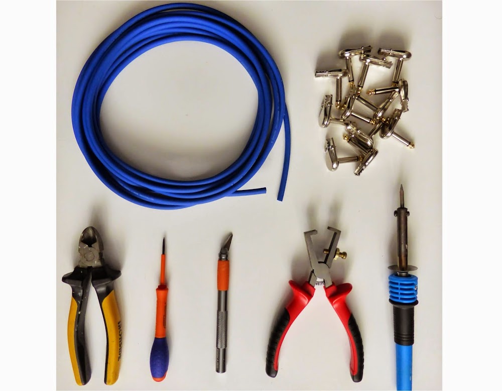
    What do you need?

    You will not need a lot of materials to make good patch cables. First, cable of course! I used Sommer Tricone MK2, mainly because it is highly flexible. Capacitance of the cable does not matter because I am using a buffer at the beginning of my chain. To choose the good cable, read my post about guitar cables.

    I used a standard cheap pancake plug that I found on Banzai Music. You can find cheap ones on ebay too. Beware that some of these pancakes are not functional, sometimes the tip and the ground sleeves are connected without any reason (2 upon 26 connectors for my Banzai music ones)... So buy a bit more that you actually need, and check them before soldering!

    Finally, you will need some classical tools: a cutter, pliers, screwdriver, a wire stripper and of course a soldering iron and solder!

    how to make patch cables guitar


    First step: cutting the cable

    Cut the cable at the correct length. To know how much length of cable you need, try to link the two pedals on your pedalboard with the cable. For side by side pedals, a 10 cm (nearly 4 inches) is enough.

    how to make patch cables guitar

    Then, you need to remove the external shielding. To know how much length you need to remove, unscrew the pancake jack plugs, and try to see how much length there is between the lugs of the jack and the part that will hold the cable.

    how to make patch cables guitar

    With a cutter or a razor blade, remove the external shielding. Do not press your blade too hard on the cable, or you will cut the ground wire. Do not hesitate to twist the cable to make it easier. You can see the shielding wire:

    how to make patch cables guitar

    Twist it, you should see the other shielding with the signal wire in the middle of it:

    how to make patch cables guitar

    Use your wire stripper to remove a bit of this shielding. Remove also a bit of the black layer: it is conductive, so you do not want it to make a false contact with the wire conducting the signal. I did not do it here because I am lazy (and have cheked that it was not making any false contact).


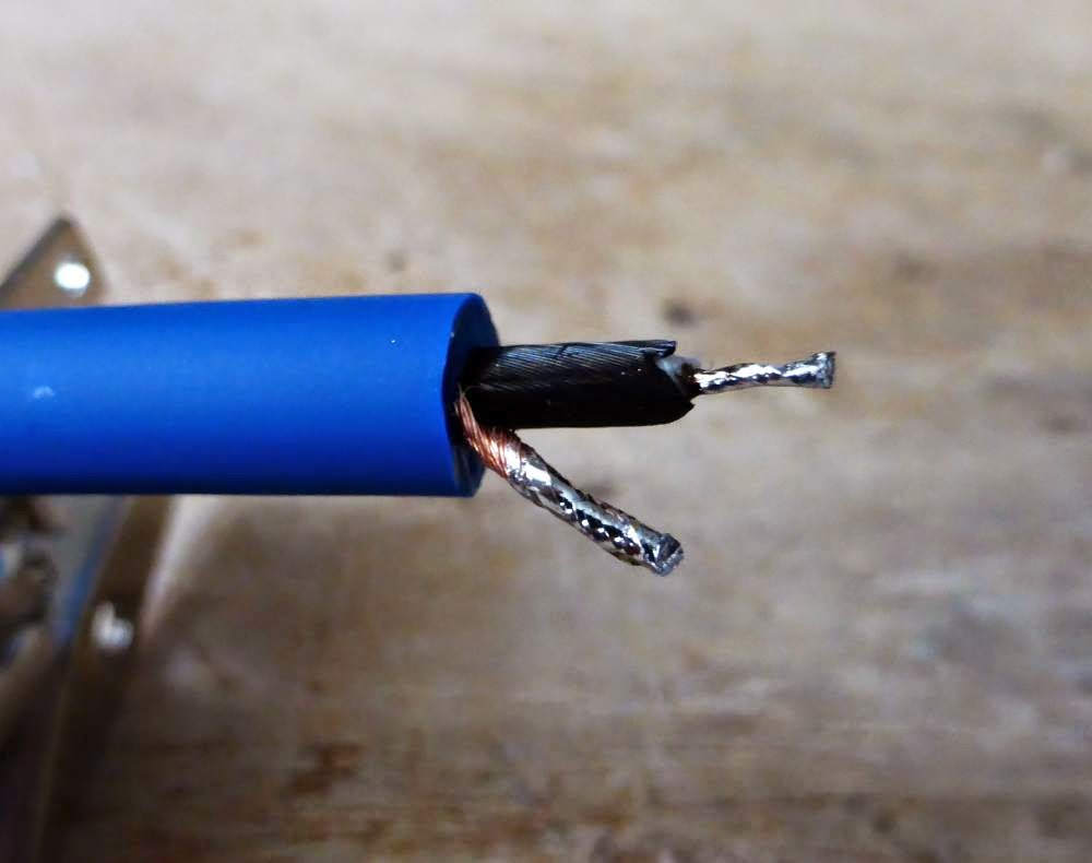
    Second step: tinning everything

    Twist the wires, and apply solder on every wire of the cable. Do not put too much solder, just enough to make it shiny. It will make soldering easier.

    how to make patch cables guitar

    Do the same on the lugs of the jack plug. Try to make small shiny solder pads:

    how to make patch cables guitar jack plug


    Last step: soldering, verifying and putting it back together

    Use a third hand to hold the jack plug and solder the signal wire to the top lug, and the ground lug to the bottom one. It is easier if you start by soldering the ground wire. Beware: the jack plug can become very hot, so do not try to hold it with your bare hands before being sure that it is cold enough.

    how to make patch cables guitar jack plug

    Before anything, check that everything is well connected and that there is no false-contact. To do that, use a multimeter in "logic" mode, and verify that there is no connection between the tip and the ground sleeve of the cable ("1": no contact, "-1" or sound: contact). Sometimes, the wires can be too close and make a false contact. If there is a false contact, try to see whether the wires are connected in the jack plug or at the other extremity of the cable (it can happen). If everything is OK, you can close the jack plug with the screws.

    how to make patch cables guitar

    Verify again with the multimeter that everything is OK. Sometimes, the tip lug can touch the top part of the plug and create a false contact. (especially if you put too much solder). Try to bend a bit the lug towards the bottom of the plug if that happen, close it and check it again.

    how to make patch cables guitar

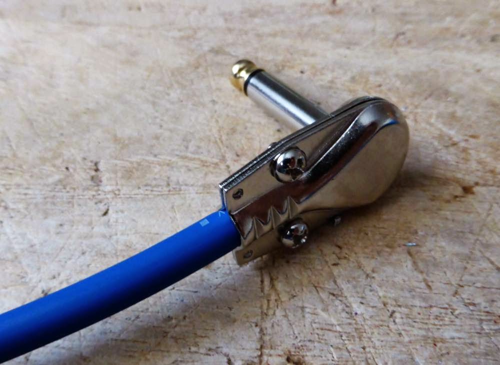
    Redo the same thing on the other side of the jack and boom! You have a perfectly fine and cheap cable!

    how to make patch cables guitar

    Here, you have it! A good patch cable, ready to go on your pedalboard!
    Was this article useful? Thank me by liking the Coda Effects Facebook page!
    Any questions? Post a comment!