 I decided to make a simple yet classy look with an aluminium faceplate and a laser engraved logo. The logo were engraved by HPM laser, very helpful and affordable! On the faceplate, I drilled the holes for three
potentiometers and I engraved letters (I painted the letters with black
ink after engravement). F = fuzz, V = volume and B = bias of course. I am really happy with the result.
I decided to make a simple yet classy look with an aluminium faceplate and a laser engraved logo. The logo were engraved by HPM laser, very helpful and affordable! On the faceplate, I drilled the holes for three
potentiometers and I engraved letters (I painted the letters with black
ink after engravement). F = fuzz, V = volume and B = bias of course. I am really happy with the result.As I was planning to sell it, I also got some "boutique kit accessories" like a small cotton bag I got on amazon and stickers that I got from Moo. Used this link to have a 10% discount: http://uk.moo.com/fr/share/#8srxpd .


HOW DOES IT SOUND?
I made a small video to test my camera. It is not the best sounding demo ever (I do not have the gear necessary to record proper demos...) but it can give a quick idea of how the pedal is sounding. Do not mind the string noise please! I will remake a proper video when I will have a bit more time. For me, this guitar pedal sounds very good, plenty of low end, and very sensitive to the guitar volume knob.
HOW DOES IT WORK?
It is the same circuit as the Sunface, with the bias knob. I already wrote a post about the Sun Face circuit, you can find the Fuzz Face circuit analysis here. The PCB follows the same layout.
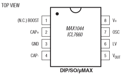
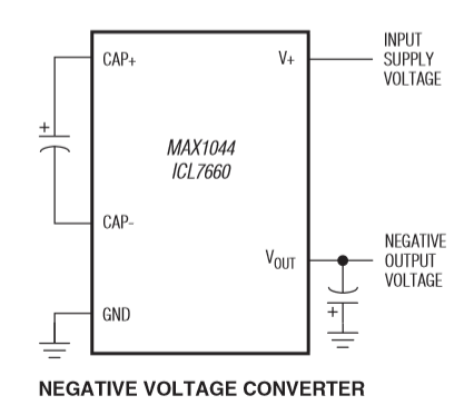
However, the power supply section is modified to accept a +9V classic power supply (finally!). For that, it uses a MAX1044 integrated circuit, which can invert the supplied voltage. Here is the schematic that we can find on the datasheet:


The voltage enters the chip through the V+ pin (number 8), and goes out inverted through the number 8 pin. The pin number 3 is connected to the ground, and a 10uF capacitor is connected between the cap+ (connected to the + lug of the cap) and cap- (Guess which side of the cap ^^). A 10uF is connected to the ground near the output voltage.
The power supply can be also a bit improved with a simple layout that you will find in many stompboxes. It is present in Scruffie's layout (without the 0.1uF capacitor)

The diode connected to the ground protects the circuit from polarity inversion. Indeed, the diode only let the current goes through in one direction (following the arrow of the scheme of the diode). So if we plug a classic center negative power supply, the ground will be 0V, and +9V will be +9V. No current will go through the diode. However, if we plug a center positive power supply (which can happen with fuzz faces that usually need center positive power supply), the ground will become +9V, and the voltage will be the ground! In a normal context, this would damage the components, and specially the transistors... However, here, the current will go through the diode straight to the +9V (ground), avoiding such trouble (quite annoying with NKT275 transistors, which worth almost 30 euros!)
The 100 ohm resistor, combined with the 47uF and 0.1uF capacitors eliminate all the residual oscillations that come from the power supply. Indeed, when the current is converted from alternating to direct, some ripples can still be there. As the capacitors only let the alternating current go through them, the alternate current will go to the ground instead of parasiting the circuit and generating "hum" noises! The different values of the capacitors are here to eliminate high and low frequencies of alternating current.
In the end, with this simple layout, we get an input voltage more stable (less noise), and a protection if someone plugs in the wrong power supply (center positive instead of negative). Which can happen with Fuzz Faces!
I hope that everything is clear! If not, post a comment!
To go further:
Geofex from +9V to -9V: an ingenious system to use the battery only when a jack is plugged in.

2 Comment
Hi , I am Still learning Please can you help . I am following the ANALOGMAN FUZZ NKT275 build from guitar FX. I have forgotten which way round the transistors go! Is Q1 close to the 33k.
AnswerHello my friend,
AnswerAre you sure about the position of the 1N4004 diode??? If you connect +9V to ground, yes, the current will flow through the diode, but the diode will produce a short circuit between the + and the - of the power supply, which means that you will burn either the power supply either the diode (or both) !!! Also, whatever happens, the voltage will remains in parallel with the rest of the circuit, which means no real protection for the transistors...
Don't you think the diode should be connected straight between (in series with) the +9V source and the 100R resistance to prevent any current flow in case the polarity is wrong?