The potentiometer: what is it?
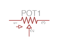
A potentiometer simply is a variable resistor! As resistors, its value is expressed in Ohms. Usually, potentiometers have a value between 1k and 10M. If you turn the potentiometer, its value will change. It has 3 lugs, named A, B and C (or 1, 2 and 3, respectively) that you can see on this picture:


Inversely, if you rotate it to the right, the resistance between B and C is reduced, and to the right it increases.
In the meantime, the resistance between A and C stays constant, and is equal to the value of the potentiometer !
So depending on what you want to use the potentiometer for, you can wire it differently. If you want the resistance to increase when the potentiometer is rotated to the right, you can wire the potentiometer between B and C:

Thus, you can replace any resistor of the circuit by a potentiometer!
And trimpots?
Trimpots are just "mini" potentiometers! It works exactly like a potentiometer, with 3 lugs, but you have to set it with a screwdriver. It is quite useful to set the value of a resistor (bias resistors for instance), without having to solder / dessolder all the time.
Logarithmic, linear? Mono, stereo?
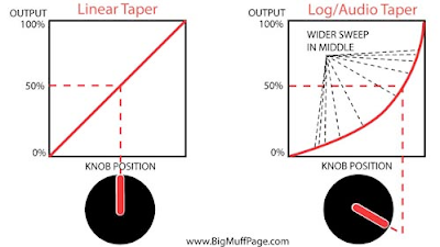
The potentiometer is characterized by its value (1k, 100k, 2M...etc.), but not only!The variation of the resistance can be linear or logarithmic (also called "audio"). When a potentiometer is linear, the resistance will vary in a linear way when you turn the potentiometer (thanks captain obvious), whereas a logarithmic potentiometer will vary in a logarithmic way. That means that the resistor will not change a lot at the beginning of the rotation, and the will vary a lot during the middle / end of the rotation.

So.... Why should I use a logarithmic potentiometer?
Two main reasons for that:
- The human ear functions in a logarithmic way: the volume is perceived in a logarithmic scale! The volume scale (decibel) is in fact a logarithmic scale. It is quite an important detail: from 95 to 96 Db, you have increase the volume a lot! So for a volume knob, a logarithmic can be better, the volume increase will be perceive as linear by our ears!
- With a log pot, the parameter will vary a lot in the higher value, which gives you more precision to set the lower values. This can be useful if you want to set precisely the lower settings, for instance with an overdrive: the low drive setting can be set more precisely, which is better if you want to have a low crunch for instance. Using an inverted log potentiometer allows you to set more precisely higher values of the pot.
Potentiometers are named differently depending on this characteristic:
- "A" = audio = logarithmic
- "B" = linear
- "C" = inverted logarithmic

A potentiometer can also be mono or stereo. A mono potentiometer is a standard potentiometer with 3 lugs. When it is stereo, there is 2 resistive tracks inside the potentiometer: it is a "doubled" potentiometer. Thus, this kind of pot have 6 pins:
It is like having two potentiometers in one! They are rarely used in guitar effects, that are mono most of the time, except in specific cases (in the Klon Centaur for instance, a stereo potentiometer sets the mix between the untreated signal and the drive signal). Sometimes it can be useful if you want one potentiometer that sets 2 different parameters in the same time.
Lets see how useful potentiometers are in a guitar pedal!
Typical uses of a potentiometer in guitar pedals
1. Setting the output volume
Most of the time, the output volume of an effect (especially with overdrives) is louder than the initial signal, especially with a boost, or an overdrive with a second gain stage that allows this volume jump.
To set the volume correctly, we can use a potentiometer, wired as a variable resistor. A part of the signal will go to the ground, whereas the rest of it will go outside the circuit. The potentiometer will split the signal in two:

Note that signal goes in through the "C" (3) lug, so Rbc increases when you turn it to the right, to make it a volume boost and not a volume cut.
This system is used in almost every guitar effect with a "master volume" knob: Fuzz Face, Big Muff, Tube screamer....
2. Gain setting
The gain of an OP amp is usually defined by two resistors (read my post about resistors in effect pedals):

The gain of the OP amp is defined by R2/R1 (inverting OP amp) or 1 + R4/R3 (non inverting). So if you replace one of the resistors by a potentiometer, you can vary the gain of the OP amp!
If you add diodes in the loop, the signal will be clipped, making it saturates. The more gain, the more clipping = more saturation! So a pot in the loop can adjust the gain of the pedal
This exactly what we can find in most overdrive circuits using OP amps! Here is an example from the gain stage of the Jan Ray pedal:

The 4 diodes will clip the signal and create saturation. A 47pF capacitor will roll off some high frequencies. The gain resistor of the inverting OP amp (R2) is replaced by R4 + a potentiometer.
If you turn the potentiometer, the resistance of R4 + pot increases, and thus it increases the gain of the OP amp, leading to more saturation!
The same schematic can be find in a Tube Screamer!
3. Replace a resistor in filters to set amount of bass / trebles
High or low pass passive filters allows to filter bass or trebles. A high pass filter let frequencies that are higher than a cutoff frequency pass, whereas the low pass filter let only pass frequencies that are lower than the cutoff frequency:


Most "Tone" potentiometers (also on your guitar!) use a low pass filter, whith a potentiometer plus a resistor to set the cutoff frequency. Here is an example from the ProCo RAT:

So here are some uses with potentiometers... Experiment and try to replace resistors in your circuit to see whether it is interesting or not!
I hope that you enjoyed this post! Do not hesitate to thank me by liking the Coda Effects facebook page!

5 Comment
just GREAT! thanks a lot!
Answerthanks!!
AnswerGreat! Thanks!
AnswerThanks for the explanation, Benoit! Would be useful to know if there is a 'standard' max resistance in volume or gain pots in a pedal : )
AnswerMy spouse and i have been very peaceful that Edward managed to finish up his inquiry out of the ideas he acquired through the web page. It is now and again perplexing to just find yourself giving away information and facts which usually some other people could have been making money from. We remember we need the website owner to be grateful to for that. All of the explanations you’ve made, the straightforward web site menu, the relationships your site assist to instill – it is all fabulous, and it’s assisting our son and us understand that topic is exciting, which is very indispensable. Many thanks for all! https://royalcbd.com/faq/
Answer