Showing posts with label Tips. Show all posts

Relay bypass with anti pop system: noiseless and clickless true bypass

Did you like my post about relay bypass? At least I did, and now I use it in almost all my pedals! Thus, they are longer lasting, and we avoid the mechanical noises of a 3PDT. However, I noticed something annoying: the relay bypass makes more "pop" noises than the 3PDT, especially with high gain circuits...

Indeed, relays tend to switch from one state to another much quicker than big mechanical 3PDT switches, which causes the "pop" noises to appear. The gainier the pedal, the more it will amplify the pop and make it louder.

So I adapted a system that I have found on Stompville that suppresses all these noises. Here is the result, with a (very) simple "before and after" video:


Ultimate guide to guitar effect wiring: how to wire DIY guitar pedals properly?

Your guitar pedal circuit is finally populated and ready to rock! However, you still have to solder all the wires... I noticed that it was during this step that beginners encounter most of the issues that go along with guitar effects making.

Especially with veroboard, you can quickly get a huge mess of wires going everywhere in the enclosure, with the so-called "spaghetti wiring" that we all achieved at least once when starting to make guitar effects!


Why you should NOT paint your guitar pedal enclosures yourself

I know this is a bit against the concept of DIY, but the more I am spray painting enclosures, the more I notice that the results are not as great as a commercialy available prepainted enclosures.

First, sanding the enclosure is a long and painful task and is mandatory if you want a clean surface to paint on. Avoid the long long hours spent carefully polishing your enclosure !

Then, a lot of thin layers are required if you want a proper painting, and most of the time, the painting will still be fragile and sensitives to shocks. I got craks or scratches on the paint really quickly... Nice if you want a beaten-up, vintage, relic look, but not if you want something really clean and durable. You will end up having something similar to the first tall font russian big muff that had paint quality issue:

Big muff tall font low quality paint

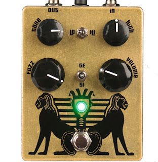
Black Arts Toneworks Pharaoh Fuzz clone

I want to make  Big Muff variants using my Coda Effects Big Muff PCB, and show you how to make them yourself. Lets start with the boutique version of the Big Muff that made it popular again on the stoner / doom scene: the Pharaoh Fuzz! Produced by Black Arts Toneworks since 2011, it was an immediate success because of the huge, warm, doomy sounds it can produce.

Here is my version:
Pharaoh Big Muff clone
As you can see, the Pharaoh has more controls than a classical Big Muff. There are the classic gain / volume / tone controls, like a classical Big Muff, plus a few other options. Here is the original version of the Pharaoh:
Black Arts Toneworks Pharaoh Fuzz
There are a "high" potentiometer that allows us to set the amount of trebles, and two switches. The first switch is a 'high / low' switch, that allow us to have 2 types of gain settings for the pedal: low gain and high gain. It modulates also a bit the trebles. Finally, you can choose the type of diodes in the last distorsion stage with the second switch: classic silicon diodes, no diodes or germanium diodes!
Black Arts Toneworks Pharaoh Fuzz clone
Finally, there are some modifications on the circuit. For instance, input and output capacitors are 10uF tantalum capacitors, which will let a looooot of bass go through the circuit!

Here is a gutshot (yes, I had fun drawing this!):
 Black Arts Toneworks Pharaoh Fuzz clone
You can see the tantalum capacitors that are drop-shaped. I try to avoid as much as possible to use it in my guitar pedals. They are not especially good for audio, expensive, and most of all there are not really "ethical friendly". Tantalum is produced from coltan, a mineral that is the root cause of many conflicts, especially in Congo. Illegal mines were opened without any regulation, degrading environment in an uncontrolled way, with many Human right issues (a bit of reading about that on wikipedia). Traceability is a big problem with electronics. Most of the time we do not know how, where or in what ecological context components are made... For tantalum capacitors, just know that they are easily replaceable by electrolytic capacitors.

Wima capacitors are much better for that: they are made in Germany (and thus, their production must respect European ecological laws and regulations). This is why I try to use them as much as possible:
 Pharaoh Fuzz clone
So, how can we make the Pharaoh from a classical Big Muff PCB?

Here is the schematic from the Big Muff page:
Pharaoh Fuzz schematic
As you can see, it is very similar to the Big Muff circuit! We can use the Coda Effects PCB and modify it following the above schematic. Here are the modifications to do:
- no mid knob, 470k for R5.
- no R2 resistor (we will use a switch instead)
- no D1/D2 diodes (switch here too)
- no R8 resistor. (replaced by a "high" potentiometer)
No big changes!

If you want, Rullywow sells a PCB especially conceived to make the Pharaoh Fuzz, named "King Tut". If these mods seems a bit difficult to do, you can buy this PCB to make it easier ! Rullywow creates really nice PCB, and this one is no exception, and is of very nice quality.

First, we will remove the mid knob by placing jumpers on the mid knob pads, like indicated on the build document.

To include the switches, we will have to use a 125B enclosure, it will not fit in a 1590B. We will have to use long lugs potentiometers to place switches so they do not touch the circuit board and create false contacts.

For R2 and D1/D2, we will use switches:
- SPDT on-on for choosing R2
- SPDT on-off-on to choose D1/D2 diodes.


Choosing R2: switching between the Hi/Lo setting of the Pharaoh

We use a "on-on" SPST. Signal arrives to the center of the switch, and goes through a resistor, 39k ("high" setting), or 390k ("low" setting):
Pharaoh mod
Try to make the connections on the other side of the PCB, it will be simpler. With this switch, you can choose the R2 value! In "high" position, there will be a lot of gain and trebles, whereas in "low" position, the sound will have more bass, less trebles.

It can apply to any resistor in the circuit, so feel free to experiment! Of course, some resistors are more interesting than others... I let you try!


Diodes choosing: 3 positions switch

We will use the same system for the diode switch. We are going to use a 3 positions on-off-on SPDT switch in order to have: germanium diodes (3 to have assymetric clipping), no diodes or classic silicium diodes. The second set of diodes to replace is D1/D2:
There it is! We have our two switches. Beware of false contacts with these switches: try to reduce the length of naked cables.Voilà ! On a déjà nos deux switchs !


Treble potentiometer

Last mod to add to have exactly a circuit like the original design: the treble potentiometer. In fact, you just have to replace R8 (tonestack resistor) by a 25k potentiometer. Just connect the lug 1 and 2 to each pad of the R8 resistor:
Pharaoh mod
It can also apply to any resistor! You can investigate to find your favorite resistor to modulate ;)
There it is! Voilà! We have got our Pharaoh Fuzz PCB!

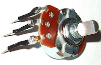
You can solder the other potentiometers now.  Beware: if we use "classic PCB-mount" potentiometer, the switches will not fit in the enclosure (they will touch the PCB and create false contacts). We will have to use "long lug" potentiometers like this ones:
long lugs potentiometer
You can also use classic potentiometer and make the lugs longer with soldered wire with solid copper wire or cur resistors / diodes lugs for instance.
long lugs potentiometer solder

You can now drill the 125B enclosure, and rock! :)
Have fun!

To go further:
Official Pharaoh webpage : if you are interested in buying the original pedal
Veroboard version of the pharaoh: a bit annoying and complex to make, but doable!
King Tut PCB: dedicated PCB conceived by Rullywow

Relay Bypass: conception and relay bypass code

You might already have heard about "relay bypass", or even used it without knowing it. It a different true-bypass system than the classical 3PDT switch. Instead of using a mechanical 3PDT switch, a soft switch, a microcontroller and a relay are combined to turn the effect on and off.

Relay bypass PCB DIY

 So... Why bother? My 3PDT switch is great, don't you think?

As you may already know, 3PDT switches are the main cause of guitar pedal failure. These switches are not particulary though, and they often break, especially as we smash it continuously with our feet on stage.

A classical high quality 3PDT switch is rated for 30,000 activation cycles. With relay bypass, we use a relay that will play the mechanical role of connecting ins and outs. Relays are usually rated between 10 and 100 millions cycles! Thus, this system is much more reliable.

Moreover, the soft switch that we use to activate the guitar pedals also last longer than a 3PDT, usually around 50,000 cycles! They are also easier to replace, as there are only 2 connections to make with the relay bypass system, and not the full 3PDT wiring.

This blog post will present you how does it work, and how to make your own relay bypass system using a microcontroller, from the beginning to the end! Long stuff (but good stuff?)!

Guitar effects and reliability: 5 things to improve to make your pedals longer lasting

I am building effects since three years, and now that it has been a while, I noticed first failures on my devices. In this article I am going to describe what are the main causes of guitar effects failures that I noticed or that people report to me, how to repair it, and how to build your pedal to make them long term lasting or easily repairable.
Oxydated chip guitar pedal


1. 3PDT switches

3PDT switches are the main reason why a pedal stops working. A broken 3PDT switch can cut your sound, and the pedal is not easy to switch on and off. 3PDT (and switches in general) are mechanical devices that suffer when activated a lot of times. Usually, good quality switches are rated for 30 000 cycles, but with the way we treat our pedal (kicking them all the time on stage), they usually fail sooner than that. Moreover, most of the times, we do not use good quality switches, but rather “China Blue” 3PDT that are not that reliable (but way much cheaper than Alpha switches).

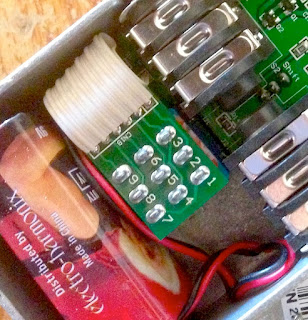
Replacing a switch is easy but sometimes quite annoying, as you have to rewire everything. To make replacement easier, you can use 3PDT miniboards and ribbon cables. This system is used in many commercial pedals, like in Electro Harmonix or even Diamond pedals:
3PDT board electro harmonix PCB

But what if you just want something more reliable? Another solution is to use relays instead of 3PDT as a mechanical system to switch the signal. A normally open momentary soft switch can be used with a microcontroller to drive a relay to switch the signal. Indeed, relays are rated for way more cycles than mechanical 3PDT. For instance a Panasonic TQ2-L 5V, which is a classical relay is rated to last between 10 and 100 million cycles! The momentary switch is really easier to replace than the 3PDT switch, only 2 cables to solder. Here is an example from the Dr Scientist Bitquest pedal (great brand!):
 Relay Bypass guitar pedal
I am planning on using this kind of system on my pedals soon. I have written a code for a PIC 12F675 microcontroller to use this kind of system. I am now designing a PCB to use it as a standard activation system, with some tricks. Also, this switching scheme is totally silent, which is nice!


2. Wiring dessoldering

When wiring the pedal, cables are not always really fixed, and the solder can break and cause a disconnection in your wiring. This can happen quite easily on the 3PDT jack where there is a lot of wiring going on, or even on input jacks. It can make the pedal mute, or generate a huge amount of noise if there are grounding issues arising from a dessoldered wire. It is easy to fix (just ressolder the wire), but quite annoying if the person cannot fix it at home (no soldering iron…etc) and needs to send the pedal over. There are two ways to prevent that. The cheap way to do it is to apply a kind of glue on the soldered wires to avoid physical stresses that cause unsoldering. This is the case in this Caline pedal (Chinese cheap clones):

Caline Reverb PCB inside
But the best way to prevent it is to include the wiring directly on the PCB, ie include the jacks and 3PDT on the PCB. It is possible to use a separate PCB for the true bypass wiring like in this JHS pedal:
JHS True bypass PCB
Or you can include the switching scheme directly on the PCB. I am planning on including it directly on the PCB on the new pedals I am prototyping. It also makes assembling easier and faster.


3. Loose jacks and 3PDT

This is a classical problem. Input jacks and the 3PDT can sometimes become a bit loose, even if you tight them with a pair of pliers. In the worst case scenario, the nut or the bolt can be lost in the process, and the pedal would be quite difficult to use if the input jack or the 3PDT “enters” inside the enclosure… It is really easy to fix, but it is a very common problem, and quite boring to repair because the customer would have to send it over (or I would have to send screws to repair it) just to fix a loose jack. There are two ways to avoid this: either your tight it a lot with a pair of pliers, either you can include jacks directly on the PCB.

However, it has one downside: if the jack input is not working anymore, it is quite boring to replace because dessoldering and ressoldering of the jack is not easy. So, do not forget to use high quality jacks like Neutrik NMJ6HCD2, and not to overcrowd the PCB around the jacks to make dessoldering possible.

I am designing my first “commercial” pedal, and I plan to include the jacks directly on the PCB. It avoids a lot of wiring (reason 2), and prevents loose jacks.


4. False contacts

If you let your PCB “free” in the enclosure, or just wire it without solid core wire (bendable wire), the circuit board can move in the enclosure. Sometimes, it can create false contacts that are quite boring to fix because you never know where it comes from. Also, it happens a lot with veroboard, where the copper side can make false contact with the bottom of the enclosure. The classical "spaghetti wiring" of beginners is also quite dangerous for that...

Guitar pedal spaghetti wiring
My recommendation would be to use PCB mounted potentiometers, which make the PCB fixed in the enclosure. If you are using a veroboard, use solid core wire to make the wiring, so you can bend it and try to fix the veroboard in the enclosure. But my ultimate recommendation would be: do not use veroboard. Honestly, it increases the risk of mistakes (misplacing components on the boards, complex wiring…), and can create false contacts easily. A PCB does not cause all this problems and is much more reliable in terms of assembling. This is why I use mostly PCB in my pedals now.


5. Component failure

Actually, I have never seen a component failure per se. Most of the failure I observed resulted from a power supply mistake. The most common case is with MAX1044 (voltage inverter / voltage doubler IC), that can only accept 10V maximum. If someone tries to apply an 18V voltage for instance, the chip simply stops working. Another thing that happens is when someone uses an inverted voltage on a pedal using a normal voltage (polarity inversion). Usually, the diode that protects the pedal from it usually just burn / melt and has to be replaced. Here is an example of a melted diode:
Burnt diode guitar pedal

For the MAX1044, I use a socket so it can easily be replaced. For the diodes, I use a “long legs” package on my PCB so I can just cut the legs of it, which makes dessoldering easier. Also, SMD components are much more difficult to replace, so I would advise to avoid it.


There it is! This are the 5 main points I noticed concerning guitar pedal failure. I am sure that you can spot other things that make your pedal fail, do not hesitate to tell me by posting a comment!
If you like this article, thank me by liking the Coda Effects facebook page, or by subscribing to the newsletter!