Showing posts with label Theory. Show all posts

All you need to know about resistors in guitar pedals

In this article (that will be part of a series of articles about the different components you can find in a guitar pedal), we will try to decipher the role of a component you surely already know: the resistor! The resistor is a simple 2-legged component. It is the basic brick of every electronic circuit, like the simplest cubic Lego brick. You will find resistors everywhere, it has many, many, many possible uses. Here, we will be interested in its role in guitar pedals.


What does it looks like?

The common resistor looks like a brown / blue cylinder, with rings of different colours and 2 legs.
metal film resistor 
Everything is about color with resistors (being color blind is quite painful with it... If you are, there is an app to help you). The overall color of the resistor indicates its composition: carbon comp are dark-brown, carbon film are beige and metal film resistor are blue / cyan like the picture above. Which ones are the best for guitar pedals? Check my post: how to choose resistors for guitar pedals.

The coloured rings allow you to know what is the value of the resistor, written in Ohms. Each colour correponds to a number:
 
Resistor color code 
Here for instance, we can read on the 3 first rings: "1", "5" and "0" = 150
The 4th number is 100, so we multiply the first value by 100 : 150 x 100 = 15000 = 15k

The last ring indicates the tolerance of the component. Tolerance is the possible maximal difference between the theoritical value indicated on the component (15k for instance), and its real value (14,99k for example). Practicaly speaking, metal film resistors that are used most of the times in guitar pedals have a 1% tolerance value (that is precise enough!), but some "precision" resistor can have tolerances down to 0.01%! They are often use in measurement devices like multimeters. In our case, 1% is really a sufficient value, there will be no audible difference if you swap a 100 ohms resistor by a 99 ohms one...

Knowing this code is not essential, you learn it gradually by practicing! If you forget, Google is here for you anyway ;)
Resistor joke

Inside the resistor, below this coloured capsule, there is a resistive film arranged as a spiral, composed of metal or carbon (carbon film or metal film!). The longer this film is, the higher the value of the resistor will be.
Resistor inside
Here for instance, the upper resistor is 27 ohms, the middle one 330 ohms and the bottom one 3.3 Mega Ohm (3 300 000 Ohms !)

The resistor has 2 symbols:
Resistor symbol
On the left is the european symbol (R5), and on the right is the american symbol (R6). It is not the only component with two different symbols. Capacitors also have different symbols between Europe and America. For resistors, I actually prefer the american symbol that evoques maybe more the role played by the resistor and the resistive strip. It is also more common to find it on guitar effects schematics.

If you want to buy cheap (but nice quality) resistors, I have this great deal.


What is its role?

A resistor, as its name suggests, resits against the flow of current. It will "absorb" a bit a current and transform it into heat. Thus, current will diminish when going through a resistor. This will diminish the voltage of the signal. The tension of the resistor is characterized this by the relationship:

U=R x I
with U = tension of the resistor (Volts), R = resistance (ohms)
and I= current intensity (amperes)

So basically, a part of the guitar signal will be absorbed to generate this tension. Thus, we can modulate the signal amplitude by modifying the resistor's value. This is really useful in a lot cases. Indeed, yout guitar signal is an alternative tension! If you want to learn more about it, read my article about electric guitar signal.

When the signal goes through a resistor, its amplitude decreases. A lower amplitude signal is simply a lower volume signal!

With a resistor, it is thus possible to reduce guitar volume! However, a resistor can only diminish the voltage amplitude. To amplify a signal, you need semiconductor devices like transistors or an OP amp.
The resistor has a lot of other applications of course! Lets see of few of them together.


How are resistors used in guitar pedals?

A resistor can have many, many applications... Here are some resistors standard applications that you can find in guitar pedals.


1. Adjusting the input or output level of an effect

Here is an example from the Big Muff circuit. An input resistor adjusts the amplitude of the input signal that will be amplified by a transistor. By changing this resistor, you can change the amount of signal entering the circuit, and thus you can change the overall gain of the pedal. Inversely, if its value is increased, the signal will be less amplified and you will have a smoother, less gainy Big Muff!

Input output resistor guitar effect
You can do the same thing at the end of the circuit to set the output volume! Usually, we use a potentiometer wired as a variable resistor, so you can adjust the final volume.

2. Pulldown resistors

When a circuit is off, some voltage can stay at the beginning the disconnected input of the circuit or in capacitors. When the pedal is turned on, the voltage goes through the circuit and causes these annoying "popping noises". To avoid that, we can add a pulldown resistor at the entry or / and output of the circuit: 

Pulldown resistor guitar effect

Generally, a resistor with a high value (like 1M) is connected to the ground on the signal path. Thus, the excess of current that goes through the circuit when the pedal is turned on is absorbed by this resistor, and you avoid these loud noises.

3. Adjusting the gain of a transistor or an Operational Amplifier

Generally, transistors or OP-amps are used in a really simple schematic that allows you to amplify the signal: common emitter / collector for the transistor, inverter or non-inverter for the OP-amp. Each of these simple schematics usually use resistors. These resistors will define the gain of the circuit.
For an OP-amp, the gain value is easy to calculate: for an inverter circuit, it will be R2/R1 and for a non-inverter circuit, it will be 1 + R4/R3. Thus, you can adjust the gain in a very precise manner! It is used in the Rub-A-Dub reverb to adjust the entry and output level of the effect.
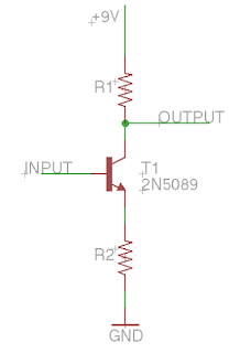
common emitter circuit transistor
For a transistor wired in common emitter like here, you can adjust the value of the resistor connected to the ground (bigger value : less gain), or to the +9V bus (bigger value: more gain). You can already use this tip in the Big Muff circuit!

4. Voltage divider

This really simple scheme allows you to adjust the voltage that you provide to some parts of the circuit.
Voltage divider
The delivered tension V1 is simply : 9V x R2 / (R1 + R2).
If you put the same value to R1 and R2, you simply divide your input tension (here, 9V) by two.
This can be really useful for some components. For instance, a lot of operational amplifiers (AOP) need a 4.5V tension to work properly. It can also be really useful to bias the base of a transistor. You can see such a scheme in the volume / output section of the Big Muff circuit.


What about potentiometers?

A potentiometer is simply a variable resistor! Any resistor of a circuit can be replaced by a potentiometer, so that the user can modify manually a value. We will see how it works in detail in another article.

Just an example: if you put a potentiometer in the loop of an operational amplifier, you can make the gain vary just by turning the potentiometer! Ideal for a volume boost, or to set the maximal amount of gain with clipping diodes. You can find such thing in the Jan Ray / Timmy circuit.

You can also put a potentiometer wired as a variable resistor to the ground at the end of the circuit, just before the output, so you can set the final volume! It is the simplest possible volume control, which you can find in many circuits, including the Fuzz Face.


An example

Lets see an example together. Here is a simple circuit, the Linear Power Booster 1 (LPB1), from Electro Harmonix. It is the first boost using a silicon transistor.

As you can see, there are five resistors (6 if we include the boost potentiometer) in this circuit. With all the things we saw before, you should be able to determine what is each resistor's role in this circuit.

The smarter guys (girls?) among us should even know which resistors to change to have more or less gain with this boost!

Some help with reading the schematic: first, try to see what path the signal is going through. For that, link the input to the output of the circuit, and you can see where the signal is going. Here, it goes through C1, Q2, C2, and then the "Boost" potentiometer. Now, you should be able to find the role of the resistors.
If you do not, do not worry! Here is some help: http://www.coda-effects.com/2015/09/lpb1-mini-pcb.html


Was this article useful? Thank me by liking the Coda Effect facebook page!
Any question? Post a comment!

Pour aller plus loin :
Nice guide from guitarPCB, about all guitar fx components.
Pulldown resistors: AMZ FX blog
Sparkfun post about resistors, easy to read and didactic. 
www.resistorguide.com: a whole website only about resistors! Great reading, highly recommended.

Rub-a-Dub Reverb (1776 Effects)

Here is my latest build, a Rub A Dub reverb! It is a really simple yet useful "always on" reverb that can go from a minimal amount of reverb to long ambient delay washes, I love it! One knob, simplicity at its finest.

Rub a Dub reverb tweed pedal
Inspired by Fender amps, I decided to cover an old messed enclosure (bad painting job) with tweed. Oldamp from guitariste.com was nice enough to give me a bit of tweed he had left from the amps he makes.

To apply the tweed, I used a pattern. Corners are especially difficult, because you need to bend the tweed (that is a rather stiff material finally) in a proper way. It was rather a long process because the glue takes quite sometimes to be perfectly dry.

The bottom plate was covered as well. I had to use longer screws in order to be able to close the enclosure! I used a plate that I found on the banzai music website, I thought it was really appropriated for the vintage fender style. There was 3 letters possible: "T", "B" or "V". "V" was the best for me, like "Verb".

Rub a Dub Reverb tweed

It was quite a tight build finally. The enclosure I used was already drilled so I - stupidly - used the same layout. Unfortunately, positioning the power supply at the top of the pedal was not a good idea, I could not directly solder the pot to the PCB. I managed to fit everything. I used gold plated jack input, so gold plated connector could - maybe - finally be useful. I am quite happy with it, because in the end, there is even enough space for a 9V battery!

Rub a Dub Reverb tweed inside

I got the PCB from 1776 effects, a builder based in the USA (1776 is the year of the independence of the USA). He sells a lot of different PCBs for different projects, from overdrives to delays (the multiplex echo machine for instance). This one is a simple, yet good sounding one knob reverb. There is also a "Deluxe" version of it with more tweakability, but for now I wanted a simple build! 

Rub a Dub reverb PCB

The PCB is really of good quality, double sided and have a nice layout. Components are spaced enough so it is not too hard to assemble, but it is compact enough to be relatively small and fit a 1590B enclosure.

Populating the board was really fun and easy, I begin to like these circuits with not too many components! For this Rub A Dub reverb, I used a Long Belton brick, Panasonic FC and SMF (except one that is a MKT standard because the value did not exist in SMF... )

How does it sound?

The "mix" potentiometer is really making a mix between the dry signal and the treated signal. So, the reverb is more or less present. It is really a nice feature, you can vary from a slight reverb in the background or a huge swampy reverb signal. I really like it at high settings. 

My only concern was that I used a Long brick, and as it is not possible to set the decay, the reverb is always very long, even when the mix potentiometer is low. If I remake one, I will use a medium or short brick. Or I will go for the "deluxe" version of the rub a dub reverb that has a potentiometer for decay using the 3rd new version of the belton brick.

I will compare with my Chasm reverb when it will be finished!


Circuit analysis

A stompbox reverb is most of the time a digital effect, simply because an analogue reverb requires a spring or plate system that is way too big for a standard 125B enclosure format. Fortunately for us, a manufacturer called Belton provides Digital Reverb modules that can be used for such projects. They are declined in 3 types corresponding to the possible duration of the reverb: short, medium and long.

Belton brick BTDR2

This brick contains a rather complicated circuit with 3 PT2399 (numeric delay chip) that follow each other with really short delay time to act as a reverb.
Belton brick schematic
Bam! I told you it was kinda complex...

They managed to make it smaller as possible with surface mounted components so we, small DIYers can use it at home to make our reverbs!
It has 6 pins:
  • Pin 1 should receive  a regulated +5V voltage
  • Pin 2 should be connected to power ground
  • Pin 3 is the input of the circuit
  • Pin 4 is the signal ground
  • Pin 5 is the output 1
  • Pin 6 is the output 2 (for stereo applications)
So it is like having another circuit in your circuit (circuitception!)
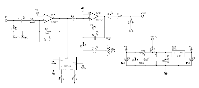
The Rub a Dub reverb is a circuit surrounding this belton brick in order to get the most of it with a simple layout. Here is the schematic:

Rub A Dub Reverb schematic 
Let's divide it in three sections:
Rub A Dub Reverb schematic
The input buffer is a simple OP amp boosting the signal before it is split between dry (analogue signal) and wet (numeric conversion and treatment by the Belton brick). First, there is a 1M pulldown resistor that prevents "pop" noises when a charge accumulates at the entry of the circuit. The excess of current is going to the ground when the effect is activated. Then, there is a coupling capacitor (22nF), preventing any parasitic direct current to go in the circuit. The signal then goes through a resistor and the first OP-amp of the TL072. The TL072 is an IC containing 2 OP amps, which is a low noise JFET amplifier.  It is wired as an inverting amplifier. Thus, we can calculate the gain of it, which is simply R3/R2 = 360/180 = 2. The OP amp multiply the signal by 2, so when it is split between the dry and wet section, it is like having 2 signals like the original one going on each side of the circuit.

The treated signal section (wet section) simply is the Belton brick circuit. The signal enters through pin 3 and goes out through pin 5 and 6. It is then mixed with two 4,7k resistors accordingly to Belton mono circuit example. The signal that goes out the brick is the reverb signal ("wet" signal).  The signal then goes back to the amplification loop of the second OP amp. First, the "mix" potentiometer sets how much wet signal is going back in the circuit to be mixed with the dry signal. So you define how much signal there will be in the final sound! A coupling capacitor prevents any parasitic DC current to go in the circuit, and a 20k resistors defines how much signal can go through at the minimum mix level. A fun mod to do is to put a switch before the 22k resistor in order to make the entire signal going through the wet section: all the signal will be treated, and you will not have a dry signal anymore, creating a "wet" reverb.

The mixing section mixes the dry signal with the wet signal using the second OP amp of the TL072. The amplification gain is around 0,5, so that the mixed signal will be of the same amplitude that the original input signal. Thus, the volume will stay constant. By modulating the resistors values, for instance the 12k resistor, volume can be increased or decreased. It is also possible to put a potentiometer there in order to have a volume / boost knob. Then the signal goes through a 1uF coupling capacitor, and there is another pulldown resistor to prevent noises, and it finally gets out!

The power supply section stabilizes the current and offers a 4,5V voltage, and a regulated +5V voltage. This is important to supply the voltage needed by the TL072 and the Belton Brick. The current enters via +9V(T), goes through a 33R resistor. A 1n4001 diode protects the circuit against polarity inversion, and a 100 uF capacitor eliminates all the residual oscillations that may come from the power supply. More details about the stabilization of the power supply in my dedicated article. On the left side of the power supply section, there are 2 resistors that act as a voltage divider. Half of the current goes through the 10k resistor linked to the ground, and half of it goes to VB. We have a 4,5V VB voltage, perfect for the TL072! On the right of the circuit, there is a 7805 REG regulator. Even if it looks like a transistor (with 3 pins), it is an integrated circuit with a simple role: a voltage between 7 and 36V can enter through pin1, and a stable 5V voltage goes through pin3. Pin2 is connected to ground. It is really convenient when you need a stable particular voltage. There are many possible versions for voltage regulators, depending on which voltage you need:
  • 78xx: positive voltage
  • 79xx: negative voltage
  • "xx": voltage value of the regulated voltage output.
There it is! I hope that everything is clear for you!
Any questions? Post a comment!


To go further:
Belton brick BTDR2H official webpage and datasheet.
Rub a Dub reverb bill of material and informations
About 7805 voltage regulator: more infos here.


    What is guitar signal?

    We hear about it all the time: it should not be degraded, you have to respect it, we can boost it, clip it or digitalize it... What are we talking about? Electric guitar signal of course! As you may know, the vibration of the strings is converted in an electric signal by your pickups, to restitute guitar sound under an electric form. How does it work? How can an electric signal encode pitches or volume? How can it be modified by guitar pedals?  

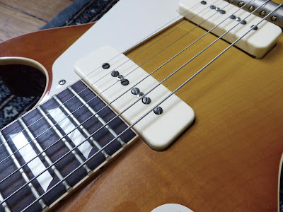
    Electric guitar pickups signal P90
    Where it all began: your guitar pickups!


    What is electric guitar signal?


    As you know, there are 2 types of currents: direct current (DC) and alternate current (AC). Direct current has a fixed value (for example, the +9V that you get from a battery), whereas alternative current oscillate between a positive and a negative value, at a given frequency. For instance, the current oscillate with a 50 Hertz (Hz) frequency on a classic house electrical outlet. 
    AC/DC logo
    Alternate current versus Direct current
    Your electric guitar signal is alternate current! The vibration of the string is captured by your guitar pickups coils, which generate an alternate current. The values between it oscillates depends on many parameters, especially your pickups output. The more the output level of your pickups is important, the bigger the amplitude of your initial signal will be.


    How is volume defined by a voltage?


    The signal amplitude (difference between the maximal and minimal voltage value) is directly linked to the volume. The greater the amplitude, the greater the volume! (and vice versa) It is as simple as that.

    Low volume High volume signal
    Most boost pedals just transform a low volume signal into a high volume one, by amplifying the signal. We can understand the origin of the word "amplifier"! It just amplifies the initial signal loud enough so that it can be heard through a speaker. It is also what happens when you strum the strings in a stronger way: the strings vibrate more and the amplitude of the signal is larger.

    Historically, amplification could be done only with tubes in the beginning (that you can find in old amplifiers or radios). When transistor was invented, it was then possible to create stompboxes capable of amplifying signal! A common collector circuit is a classic layout that you will find in many circuit, for instance in the big muff circuit. Today, with integrated circuits, it exists smaller op-amps that can amplify the signal with one simple chip! Some of these chips / recent transistors even use almost the same technology as tubes to amplify an audio signal (FET/MOSFET burr brown for example).

    Amplification guitar components
    100 years of evolution of signal amplification in one picture: a 12AX7 tube, an AC188 germanium transistor, a 2n5089 silicon transistor and a TL072 integrated circuit OP amp

    To reduce the signal amplitude (and thus the volume), a simple resistor is enough! That is why there is generally a potentiometer wired as a variable resistor at the end of a circuit to set the output volume. You can find this in many many circuits, like in the Jan Ray.


    How alternate current can define a note or pitch?


    As we have seen above, alternate current is characterized by a period, which defines a frequency (frequency = 1/period), written in Hertz (Hz). For example, alternate current in an electrical outlet has a frequency of 50 Hz.
    Each note has also a frequency! For instance, you may have heard of the 440 A that is the standard pitch used as a reference for many instruments. It is named like this because of its 440 Hertz frequency!

    The higher the frequency of oscillation of the current, the higher the pitch is.
    alternate current pitch
    Thus, each note is defined by its frequency. By modifying the frequencies, the sound can be modified. The characteristic sound of a wah wah is due to the fact that it will only let some frequencies go through it. The "ducky" sound that you get in the middle position of a wah is due to the fact that it lets pass only mediums frequencies. Tone potentiometers also affect frequencies by eliminating high frequencies (diminishing trebles) or low frequencies (less bass).

    Human ear can perceive frequencies between 20 and 20 000 Hz. Practically speaking, it also depends on individuals. With aging, higher frequencies are less and less heard. It is interesting to note that medium frequencies between 1000 and 4000 Hz are perceived louder for a same volume (in decibel). Which is nice for us, guitarists, because electric guitar has a lot of output in these frequencies! And this is how guitarists became famous and not the bassists! (duh!)

    Of course, it is a bit more complicated than that. When you play a note, there are many frequencies that are played at the same time, and not only one (harmonics for instance). When you play chords too! When several frequencies are played at the same time, voltages are simply added.


    What are effects doing to your signal?

    Lets see a few examples of how effects modify your electric guitar signal.

    1. Compressor
    Compressors delimit a maximal amplitude for your signal. By diminishing the amplitude, you "compress" the sound! (all names make sense now, right?)
    Compressor effect on guitar signal
    You can see here that the original signal has a lot of variations of volume: there is a lot of dynamic. However, when a compressor is used, signals are closer to each other: a bit of dynamic is lost. A compressed guitar signal actually sounds very good, that is why many guitarists use a compressor, with a price to pay: you loose a bit of dynamic.


    2. Saturation: overdrives, fuzz, distortions...
    Saturation happens when the top and bottom of the signal are clipped. This can be done with different ways: saturation of tubes, transistors, using diodes that will let some voltage go to the ground...etc.
    Saturation electric guitar signal
    We can clearly see here that the top of the signal curve has been cut: the signal was clipped. To better understand what happen here, read my article about the Vemuram Jan Ray circuit. Diode clipping is explained in it.
    We can also see that the more the signal is saturated, the more it is compressed! This is something you can clearly hear when you use too much saturation for your guitar, or for instance with a big muff.


    3. Numeric versus analogue signal
    The biggest difference between a numeric and an analogue signal is that an analogue signal can have an infinity of values between 0 and 1, whereas numeric signal is limited because of its binary nature (only 1 and 0...). An analogue signal with an infinite value of 3.3333333...etc. can exist, however a digital signal will stop at some point depending on the quality of it. This quality of the digital signal is generally expressed in bits / kbits per second. A mp3 has a quality between 64 and 256 kbits per second. A CD is 1411 kbits/sec.

    So you have a fixed number of points / seconds. The possible values of these points depend on the encoding quality.
    Analogic versus numeric audio signal

    The sampling rate also defines the numeric signal quality. The higher it is, the most precise your numeric signal will be (and will not generate noise).
    Thus, we can understand why people did not really liked numeric effects at some point. The "coldness" of the sound that you can feel with a numeric pedal comes from this encoding process.

    However, today, technology have evolved so much that encoding can be done without an audible quality loss.

    For instance, the first digital delay, the Boss DD2, had a 12 bits converter, with a sampling rate of 32kHz (just near radio quality...). Today, Strymon uses 24 bits converter with a 96kHz sampling rate (DVD audio quality!)


    Here it is, I hope this article has enlightened you a bit about this mysterious "signal"... If you liked this article, thank me by liking the Coda Effects Facebook page!

    Any questions? Post a comment!


    To go further:
    Analogue versus numeric signal: detailed analysis about differences between analogue and numeric guitar signal by Screaming FX
    A bit of theory about compression, clipping...etc.

    Big Muff Ram's Head clone (73 version)

    Here is the Big muff Ram's Head clone I have made recently. The Ram's Head is one of the most iconic Big muff models. Produced in 1973, it was the second issued version of the Big Muff, just after the Triangle model. Multiple versions of the Ram's Head existed until 1977, including the "violet era" Ram's Head that sells around 1000 dollars on ebay! The Ram's Head v2 is well known as it was used by Pink Floyd's guitarist, David Gilmour. He used the Big Muff combined with a boost in order to have a nearly infinite sustain during some solos, like the famous Comfortably Numb's one.
    EHX 73 Ram's Head clone
    I decided to make this version, with a PCB from musikding. I am currently prototyping a double sided PCB to use it in 1590B enclosures. Here, the PCB is single layer, so I had to use a 1590BB enclosure. I polished the enclosure with sandpaper 140, then 400 and 800 to have a thin polish, following the same direction to make it look like brushed aluminium. I washed it with acetone, and add 2 layers of satin varnish to avoid corrosion.
    EHX 73 ram's head clone
    I followed the classic scheme of a 73' Ram's Head Big Muff (Gilmour!). I used Wima MKP2 capacitors and one electrolytic to stabilize the power supply. I added two switches to control the amount of mids (switch 1) and bass/trebles (switch 2). The first switch allows you to change the 4,7nF capacitor of the tone stack for a 10nF, thus increasing mids. The other switch plays on the resistor and capacitor at the entry of the circuit, giving us 2 options: a very bassy / smooth one which is the classical ram's head, perfect for doom or stoner rock, and another more trebly, gritty and scratchy!
    EHX 73 ram's head clone
    With the PCB, it was quite easy to organize the wires inside the enclosure. With a BB sized enclosure, there is a lot of room!


    How does it sound?

    I did not have time to records samples of this pedal. You will have to believe me then! However, no surprise with this one, it sounds like... a Big Muff! Heavy, oversaturated, compressed, ideal to generate walls of saturation. Ideal for stoner, I played it during almost one hour, playing some Kyuss, Fu Manchu, Queen of the Stone Age whereas I just wanted to test it quickly! The tone potentiometer is really efficient and allows you to go from a bassy heavy sound to something more gritty and aggressive. The bass switch is also really efficient, on one side you have a classic ram's head with a lot of bottom end, quite smooth in the highs, and something more gritty on the trebles on the other side of the switch. The mid switch is also quite efficient, we can hear that sound is more "full" when switched on, and it really works well in a band situation. I am really happy with the result, it is exactly what I was expecting!


    How does it work?

    The Big muff is one the favourite circuit of guitar pedal builders (with the Tubescreamer). Indeed, its circuit is really well known, there is a lot of information available all around the internet, and it is really easy and fun to modify! Each component plays a particular role, and changing it for a different value will change the overall sound of the pedal without damaging the circuit most of the time. It is one of the most cloned guitar pedal, by DIYers or by boutique companies: Mojo Hand FX, Earthquaker Devices, Pete Cornish... Almost every brand has its version of the big muff!
    Big muff boutique pedals
    Attack of the clones: all the pedals in this picture are Big Muffs 
    or "heavily inspired" by the Big Muff pedal

    Technically the Big Muff is not a fuzz but a distortion with most of the saturation coming from diodes. However, it has 2 distortion stages, causing the heavily compressed and saturated sound of the Big Muff. The sound is finally close to a fuzz. Lets have a look on the circuit schematic:
    EHX 73 ram's head circuit schematic

    I know, it seems horrible and over complicated... Too many components! But lets divide it in 5 sections:
    EHX 73 ram's head circuit schematic
    Big muff input section
    The first section (input section) is simply a buffer to adapt the impedance of the guitar to the first distortion stage, and which amplify also the signal. As OP amp did not exist at that time (1973, remember?), this is made with a transistor wired in common emitter. Today, a simple OP-amp would be enough! First, there is an input resistor which will diminish a bit the amplitude of the signal. Then, a coupling capacitor will remove any parasitic DC current that mights come from the guitar. Changing the values of the coupling capacitor and input resistor can changes the amount of bass and trebles of the big muff. That is how I made the switch on the pedal. A bigger value resistor and a higher capacitance for the coupling capacitor will increase the bass response of the unit. Then, a transistor wired in common emitter will amplify the signal. Depending on the amplification of this stage, the saturation will be more or less important. The amplification is set by the different resistors on this circuit. Changing resistor's values can increase or decrease the overall gain of the unit. Next, there is a coupling capacitor (again), and a potentiometer wired as a variable resistor that will allow the user to set the amplification on this stage = gain of the Big muff! 

    Big muff circuit saturation
    The second and third part (first and second clipping second) are in fact exactly the same circuit. It is used to distort the signal, through the clipping induced by diodes. There is first a coupling capacitor (if you look carefully there is one at each section's start except the tonestack), followed by a resistor. Then, there is a transistor wired in common emitter like in the first part of the circuit with resistors to define its gain. A 470pf capacitor will allow more or less trebles to go through the section. Changing the three 470pF capacitors for a larger value (like 560pF) will diminish the trebles of the unit. This is the case in many clones, like in the Iron Bell from Mojo Hand FX for instance. The diodes will clip the signal and generate the saturation. In classical Big Muff, silicon diodes are used, but in some "boutique" clones, germanium diodes clip the signal (pharaoh fuzz for instance). With germanium diodes, there is less volume, and the sound is even more compressed and saturated! For more infos about diode clipping, read my article about the Jan Ray circuit.


    The third part of the circuit is for me the most important part, the tonestack! This little circuit is what gives the characteristic sound of the Big Muff, and the medium loss, the enemy of guitarist playing in a band. Indeed, when you loose mediums, you litteraly disappear from the mix, as if the guitar was muted! A lot of mods do exist to avoid that: a switch which modify the values of the resistor linked to the ground or the 4,7nF capacitor (which I did on this Big Muff), or to use a potentiometer instead of a resistor, and modify the values of the components to have flat mids, to have a proper medium knob (AMZ tone stack). It is also possible to replace the tone stack by another one, like on the Pete Cornish G2. You will loose the Big Muff style distorsion for a much classical overdriven sound. You can even remove it! You will then have an "in your face" sound with a lot of mediums. You can find this system on the Dwarcraft Eau Claire Thunder for instance. Experiment by yourself, the tone stack is a simple circuit and changes a lot the sound of the Big Muff. A lot of fun! 

    Big muff output section
    Finally, in the output / volume section, the signal is amplified again (to prevent volume loss due to the diodes clipping). It uses a transistor wired in common emitter biased to have a strong amplification. A coupling capacitor is present, followed by a potentiometer wired as a variable resistor to modulate the output signal amplitude. We can recognize (again !) the volume control of a fuzz face!

    I really advise you to make a muff once. It is really fun to make and to mod. After reading the Big Muff page, you will know exactly what to change to make it sound like you always wanted!

    To go further:
    Big muff Page: THE website about big muffs! All the versions, schematics and more! A must read for muff lovers.
    Big muff pi circuit analysis (electrosmash): precise analyse of the circuit
    AMZ tone stack: study about the big muff tonestack, alternative tone stacks
    Big muff mods and tweaks: Some easy mods for your big muff. They are easy but funny mods!

    All you ever wanted to know about guitar cables (but were afraid to ask)

    Recently, guitar entered the mysterious and magical world of audiophiles. The kind of world where you can buy carbon turntables for 30 000 pounds (yes), anti seismic isolation racks, or cables for 14 000 pounds! Of course, all these expensive devices highly improve the purity and detail of the sound, and finally allow you to listen to mp3 like you should! (Irony inside) Do you recognize the phenomenon? Yes, this is the same thing with guitar, the quest for "THE sound", with expensive guitar pedal effects and cables! Fulltone, George L's, Evidence Audio, Monster Cables... A lot of new "luxury" cable brands! Is there really a difference? What are the characteristics of a "good" cable? How much should it cost?

    First, lets demolish some myths about guitar cables together.


    Guitar cables myths and legends

    1. Gold-plated jack
    This first legend around cables comes from the fact that gold is often use in high quality conductors (computers, HiFi...etc), because the conductivity of gold is better than a lot of other metals, and because gold does not corrode. So we would expect an optimal transfer between the jack and the jack input of your amp, guitar pedal...etc. However, 99.999% of effect, amps or guitars have nickel-plated jack inputs! Therefore, the conduction value will be the one of the lowest conductor, that is to say nickel. Moreover, the conduction value of gold compared to nickel is not that much different.
    What is more is that gold is a soft metal, the plating quickly wears off the jack when you plug / unplug it a lot. So the gold plating will not corrode (neither will nickel plating anyway, unless you wait for many many many years...), but will goes off the jack! Unless you have a massive gold jack plug (sell your house if you want a pedalboard with those ^^)

    gold plated jack vs silver nickel
    Here, we can clearly see that only the tip of the jack is gold-plated
    Moreover, in most cases the plating is not pure gold
    (and surely not for this 0,7 Euros Chinese jack plug)
      
    2. The cable itself is special
    Almost every cable that you can buy comes from big suppliers that are always the same: Sommer, Mogami, Belden... Recreating a cable would be too expensive for a manufacturer. Almost every cables manufacturers use Sommer, Cordial...etc, and most of the cables you will find in the shops are rebranded cables. That does not mean that they are bad cables, it just mean that you should not have to pay more for a cable because the shielding is supposed to be unique and specific to one brand. However, there are exceptions. For instance, George L's has a specific cable production.
     
    3. This cable has more low end / mids / respects the whole guitar spectrum
    The only things that can be degraded in your cables are the trebles. Indeed, as we will see later, cables behave like a capacitor, with a small capacitance in picofarads.
    Or, this capacitor acts in the RLC circuit formed by your pickups, resistors (internal resistance of the pickup, volume and tone pots), and will eliminate trebles.
    The formula to calculate the total capacitance of the cable is:
      Total capacitance = capacitance /meter * total cable length
    So, the higher the capacitance of your cable is (so the longer it is), the more you will loose trebles! However, this only acts on treble (it behaves a bit like a low pass filter), so there will be absolutely no influence on the low end / mids!

    Fulltone cable lies

    Screen capture of Fulltone website. They openly say that cables modify low end and mediums (and that their cables are the best of course) This is clearly all about marketing, and also a lie.


    What is a good cable then?

    Here is the anatomy of a guitar cable: (picture is Sommer Tricone XXL that I used for my post: how to make guitar cables step by step tutorial)
    Guitar cable structure  

    You can see that the shielding and the central conductor are separated by 2 insulation layers. One layer prevents the accumulation of electrostatic charges that can happen when the shield rubs the insulation layer. The insulation layer isolates the ground shielding from the copper conductor. These two layers form a capacitor between the ground and signal:

     guitar cable composition
    The capacitance value of this capacitor depends on the nature of the cable and its length: materials used for the insulation, diameter and thickness of these materials, diameter of the conductor...etc. The problem is that there are many trade off between these parameters: a very good insulating material can be very stiff and thus makes the cable not very flexible, the conductor can have a big diameter but then the cable will be more fragile...

    This capacitor will act on the RLC circuit constituted by the guitar pickup, its internal resistance (plus the resistance of the volume and tone pot). That will change the frequency response of your guitar, mostly by eliminating trebles. The more the capacitance value is high, the more you will loose the highest part of your guitar spectrum. Some people actually like to use high capacitance value to eliminate high frequencies and boost a bit the high mids (typically people using Stratocaster guitars). This is a strategy I would not recommend because the trebles are definitely lost, whereas it is possible to modulate the frequencies with an EQ, boost, or your tone pot that here for a reason right?

    Cable capacitance trebles loss guitar
    Differences between a high capacitance (600pF-pointed by the arrow) and low capacitance cable. The high capacitance cable boosts a bit the high mids, but your loose a lot of trebles (from Effectrode)

    The formula to calculate total capacitance of a cable (quoted above) shows that total capacitance also depends on the length of the cable. A cable twice as long as another one has a doubled capacitance.

    The characteristics of a good cable are thus simple:
    • A low capacitance per meter. Generally speaking, 80 pF/meter (24.4 pF/foot) is considered to be a very good value. Below that, it is of course even better!
    • Shortest length possible! It depends of course of your mobility on stage. The shorter the better.
    • Rugged against shocks, twisting, stepping, everything that can happen to a cable during a gig... However this is not really necessary for your patch cables on your pedalboard. A very flexible cable will be much more fitted for this use.

    Finally, you do not need so much to have a good cable! What about good jack plugs? Their role will be mainly to be rugged. Take resistant ones. For instance, Amphenol or Neutrik jack plugs are a good standard and will perfectly do the job. Remember: you do not need gold!

    A lot of brands do not say what is the capacitance per meter value of their cables, even if it is the most important value (the only one?) to look at when you want a good cable! If it is not written somewhere on their website, they are probably not a serious cable brand... Buying a cable without knowing this value would be like buying a sport car without knowing its engine, performances or handling!


    What is the best signal chain?

    In theory, the best configuration would be:
    • active pickups, then as many cable as you want!
    Indeed, active pickups have a low impedance output, so the effect of the cable capacitance will be negligible. It is like having a buffer built in your guitar!
    However, the guitarist is very conservative and does not like to use batteries in his guitar (myself included). Moreover, some guitar effects do not react well to a low impedance signal (fuzz faces for instance) You will have to use passive pickups with high impedance output, whose signal might be degraded by the cables. You will have to minimize the treble loss between the lead cable and your fuzz, then from the fuzz to the first buffered pedal. The ideal configuration would then be:

    • Passive pickups, shortest cable possible with a low capacitance, fuzz, short cable with a low capacitance, then buffered pedal, and as much cable as you want
    The best is to have a cable called the "lead cable", with a low capacitance, and short as much as possible, that links your guitar to your first high impedance effect. 
    Best signal chain guitar cables
    So the best is to find a resistant low capacitance cable that will be used between your guitar and high impedance effects. To know if an effect needs high impedance to sound great, you have different options. You can look on the datasheet of the effect (usually, manufacturers give it). If it is under 500k lets say, it is a high impedance effect. You can also try to put a buffered pedal before it and try to hear if it makes any differences. If there is no audible difference, you can consider it a low impedance effect.


    But then, what is the best guitar cable?


    Here is a table with the capacitance per meter (or per foot) of many guitar cables that you will find on the market.
    Cable name Capacitance
    Sommer Spirit LLX 52 pF/m / 15.9 pF/ft
    Van Damme Silver Series Lo-Cap 55 pF/m / 16.8 pF/ft
    George L's .155 / .225 67 pF/m / 20.4 pF/ft
    Klotz AC110 70 pF/m / 21.3 pF/ft
    Mogami 3368 70 pF/m / 21.3 pF/ft
    Sommer Classique 78 pF/m / 23.8 pF/ft
    Sommer Spirit 78 pF/m / 23.8 pF/ft
    Cordial CGK 122 82 pF/m / 25 pF/ft
    Sommer Tricone MKII / XXL 85 pF/m / 25.9 pF/ft
    Cordial CGK175 88 pF/m / 26.8 pF/ft
    Van Damme Silver Series Flat-Cap 90 pF/m / 27.4 pF/ft
    Adam Hall KIK122 95 pF/m / 29 pF/ft
    Klotz AC106 95 pF/m / 29 pF/ft
    Klotz AC104 115 pF/m / 35.8 pF/ft
    Sommer Colonel Incredible 130 pF/m / 39.6 pF/ft
    Mogami 2524 130 pF/m / 39.6 pF/ft
    Belden 9778 148 pF/m / 45.1 pF/ft
    Free The Tone CU-416 160 pF/m / 48.8 pF/ft
    Belden 8412 190 pF/m / 57.9 pF/ft
    You can already notice that there is no link between the prices and the capacitance of the cables... (cf Free the Tone...)

    For the lead cable & cables before the first buffered pedal

    With the chart above, we can see that the cable with the best characteristics is the Sommer Spirit LLX. Sommer conceived this cable especially for guitar. It has an incredibly low capacitance per meter, combined with a good resistance, and a good flexibility. However, it is still quite thick, so it might not be the best cable for a pedalboard. It is a bit more expensive than other cables, but it is reasonably priced (around 2,5 euros / meter).
    George L's .155 cable is really thin and flexible, and has a good capacitance per meter value, ideal for pedalboard use. However, it is quite expensive (around 6 euros per meter). As patch cables are short anyway, the difference with another cable like Sommer Tricone MKII might not be perceptible. The Tricone MKII is also incredibly flexible.

    For pedalboard patches, after a buffer or a buffered pedal.
    Now that capacitance does not matter anymore, you can pick whatever cable you want. For me, I chose the Sommer Tricone MKII that is really flexible, thin and quite cheap (less than 1 euro / meter). In this case, only the flexibility of the cable will be important, in order to be able to make short and aesthetic patch cables.

    For the effect loop - using a double cable
    When you use the effect loop of your amp, your setup can start to be a bit messy, as it requires already 4 cables to handle: lead cable towards your pedalboard, output of the pedalboard to the amp, and the 2 cables of the effect loop! To avoid such a mess, I use a double cable, the Sommer Onyx 2025. For the effect loop, you do not need low capacitances because the impedance is already low. Thus, you will have one cable instead of two, which is much cleaner looking.

    My final advice would be: do not trust brand marketing, check the numbers (measure them if you want to! Science, bitch!), ask for the capacitance per meter/foot, and make the cables yourself!
    No cable should cost more than 20 euros if you make it yourself!

    Good news is: I made a step by step tutorial about how to make guitar cables.

    There it is! I hope this post was useful. If you liked this article, thank me by liking the Coda Effects Facebook page!
    Any questions? Suggestions? Disagreement? Post a comment!


    To go further

    Shootout Cables UK : great website with a lot of informations about cables.
    Very good guide (pdf) with a lot of answered questions about cables from ProCo sounds.
    Ovnilab.com : great article about frequency response of guitar cables.