Showing posts with label Tips. Show all posts

Resistors: which one to choose?

When I started building guitars effects, I had a very hard time deciphering which components to use. I was quite scared of using the wrong component. Lost and impatient, I chose the resistors a bit randomly.

Too bad, they were more than one inche long! And of course they did not fit.

I was so disappointed.

Now, I have decided that this should not happen to other beginners. Here is my guide to choose the correct resistors for building guitar effects.

Every component has a nearly infinite number of variations, and so does resistor, which is the most simple of them! You can find resistors of all shapes and colors on the market today...


It is easy to be lost with all this possibilities! No worries, it is quite easy to find what we need by considering all the different characteristics of a resistor:
  • Its value (in ohms)
  • How much power they can handle (W)
  • Its composition
  • SMD or classic component?
We can already avoid the SMD resistors, not very suited for our use. They can be very, very small and hard to solder. They can be useful to fit big circuits in small enclosures though. For advanced builders only!

Acceptable power can allow us to eliminate a high number of candidates. Indeed, in our stompboxes, the power delivered by the power supply is really low.

Resistor resisting to 0.25W (the famous 1/4W resistor) will be enough. 1/8W can be used too in some cases. However, the classic resistor used in guitar pedal is 1/4W so I would recommand to stick with it, unless you need to save space. So we are already with our classical cylindrical resistor with two legs!

 Next, we have to choose resistor type:
  • Carbon comp resistor: dark brown resistor, they are also quite big. They were used in old vintage circuits from the 60s. They are useful if you want to replicate a vintage circuit with all its details. In other cases, they are not particulary good: they are big, quite noisy and expensive (because of "mojo").
  • carbon comp resistor 
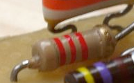
  • Carbon film resistor: light brown coloured, they usually have a 5% tolerance value. That means that their real value can be 5% different from the theoritical value. (it is not a lot) They also are quite cheap.
  • Carbon film resistor
  • Metal film resistor: the blue ones! They usually have a 1% tolerance. They also are cheap, and are the standard resistor that you are going to find almost everywhere. Moreover, they are less temperature sensitive, and noiseless!

It is then quite obvious that, unless if you want to reproduce perfectly a vintage circuit or to diminish costs (anyway, metal film resistors are super cheap too!), the 1/4W metal film resistors are the best choice to begin! Here is a good deal to have 1280 resistors of different value for a ridiculously small amount of money!

All you ever wanted to know about guitar cables (but were afraid to ask)

Recently, guitar entered the mysterious and magical world of audiophiles. The kind of world where you can buy carbon turntables for 30 000 pounds (yes), anti seismic isolation racks, or cables for 14 000 pounds! Of course, all these expensive devices highly improve the purity and detail of the sound, and finally allow you to listen to mp3 like you should! (Irony inside) Do you recognize the phenomenon? Yes, this is the same thing with guitar, the quest for "THE sound", with expensive guitar pedal effects and cables! Fulltone, George L's, Evidence Audio, Monster Cables... A lot of new "luxury" cable brands! Is there really a difference? What are the characteristics of a "good" cable? How much should it cost?

First, lets demolish some myths about guitar cables together.


Guitar cables myths and legends

1. Gold-plated jack
This first legend around cables comes from the fact that gold is often use in high quality conductors (computers, HiFi...etc), because the conductivity of gold is better than a lot of other metals, and because gold does not corrode. So we would expect an optimal transfer between the jack and the jack input of your amp, guitar pedal...etc. However, 99.999% of effect, amps or guitars have nickel-plated jack inputs! Therefore, the conduction value will be the one of the lowest conductor, that is to say nickel. Moreover, the conduction value of gold compared to nickel is not that much different.
What is more is that gold is a soft metal, the plating quickly wears off the jack when you plug / unplug it a lot. So the gold plating will not corrode (neither will nickel plating anyway, unless you wait for many many many years...), but will goes off the jack! Unless you have a massive gold jack plug (sell your house if you want a pedalboard with those ^^)

gold plated jack vs silver nickel
Here, we can clearly see that only the tip of the jack is gold-plated
Moreover, in most cases the plating is not pure gold
(and surely not for this 0,7 Euros Chinese jack plug)
  
2. The cable itself is special
Almost every cable that you can buy comes from big suppliers that are always the same: Sommer, Mogami, Belden... Recreating a cable would be too expensive for a manufacturer. Almost every cables manufacturers use Sommer, Cordial...etc, and most of the cables you will find in the shops are rebranded cables. That does not mean that they are bad cables, it just mean that you should not have to pay more for a cable because the shielding is supposed to be unique and specific to one brand. However, there are exceptions. For instance, George L's has a specific cable production.
 
3. This cable has more low end / mids / respects the whole guitar spectrum
The only things that can be degraded in your cables are the trebles. Indeed, as we will see later, cables behave like a capacitor, with a small capacitance in picofarads.
Or, this capacitor acts in the RLC circuit formed by your pickups, resistors (internal resistance of the pickup, volume and tone pots), and will eliminate trebles.
The formula to calculate the total capacitance of the cable is:
    Total capacitance = capacitance /meter * total cable length
So, the higher the capacitance of your cable is (so the longer it is), the more you will loose trebles! However, this only acts on treble (it behaves a bit like a low pass filter), so there will be absolutely no influence on the low end / mids!

Fulltone cable lies

Screen capture of Fulltone website. They openly say that cables modify low end and mediums (and that their cables are the best of course) This is clearly all about marketing, and also a lie.


What is a good cable then?

Here is the anatomy of a guitar cable: (picture is Sommer Tricone XXL that I used for my post: how to make guitar cables step by step tutorial)
Guitar cable structure  

You can see that the shielding and the central conductor are separated by 2 insulation layers. One layer prevents the accumulation of electrostatic charges that can happen when the shield rubs the insulation layer. The insulation layer isolates the ground shielding from the copper conductor. These two layers form a capacitor between the ground and signal:

 guitar cable composition
The capacitance value of this capacitor depends on the nature of the cable and its length: materials used for the insulation, diameter and thickness of these materials, diameter of the conductor...etc. The problem is that there are many trade off between these parameters: a very good insulating material can be very stiff and thus makes the cable not very flexible, the conductor can have a big diameter but then the cable will be more fragile...

This capacitor will act on the RLC circuit constituted by the guitar pickup, its internal resistance (plus the resistance of the volume and tone pot). That will change the frequency response of your guitar, mostly by eliminating trebles. The more the capacitance value is high, the more you will loose the highest part of your guitar spectrum. Some people actually like to use high capacitance value to eliminate high frequencies and boost a bit the high mids (typically people using Stratocaster guitars). This is a strategy I would not recommend because the trebles are definitely lost, whereas it is possible to modulate the frequencies with an EQ, boost, or your tone pot that here for a reason right?

Cable capacitance trebles loss guitar
Differences between a high capacitance (600pF-pointed by the arrow) and low capacitance cable. The high capacitance cable boosts a bit the high mids, but your loose a lot of trebles (from Effectrode)

The formula to calculate total capacitance of a cable (quoted above) shows that total capacitance also depends on the length of the cable. A cable twice as long as another one has a doubled capacitance.

The characteristics of a good cable are thus simple:
  • A low capacitance per meter. Generally speaking, 80 pF/meter (24.4 pF/foot) is considered to be a very good value. Below that, it is of course even better!
  • Shortest length possible! It depends of course of your mobility on stage. The shorter the better.
  • Rugged against shocks, twisting, stepping, everything that can happen to a cable during a gig... However this is not really necessary for your patch cables on your pedalboard. A very flexible cable will be much more fitted for this use.

Finally, you do not need so much to have a good cable! What about good jack plugs? Their role will be mainly to be rugged. Take resistant ones. For instance, Amphenol or Neutrik jack plugs are a good standard and will perfectly do the job. Remember: you do not need gold!

A lot of brands do not say what is the capacitance per meter value of their cables, even if it is the most important value (the only one?) to look at when you want a good cable! If it is not written somewhere on their website, they are probably not a serious cable brand... Buying a cable without knowing this value would be like buying a sport car without knowing its engine, performances or handling!


What is the best signal chain?

In theory, the best configuration would be:
  • active pickups, then as many cable as you want!
Indeed, active pickups have a low impedance output, so the effect of the cable capacitance will be negligible. It is like having a buffer built in your guitar!
However, the guitarist is very conservative and does not like to use batteries in his guitar (myself included). Moreover, some guitar effects do not react well to a low impedance signal (fuzz faces for instance) You will have to use passive pickups with high impedance output, whose signal might be degraded by the cables. You will have to minimize the treble loss between the lead cable and your fuzz, then from the fuzz to the first buffered pedal. The ideal configuration would then be:

  • Passive pickups, shortest cable possible with a low capacitance, fuzz, short cable with a low capacitance, then buffered pedal, and as much cable as you want
The best is to have a cable called the "lead cable", with a low capacitance, and short as much as possible, that links your guitar to your first high impedance effect. 
Best signal chain guitar cables
So the best is to find a resistant low capacitance cable that will be used between your guitar and high impedance effects. To know if an effect needs high impedance to sound great, you have different options. You can look on the datasheet of the effect (usually, manufacturers give it). If it is under 500k lets say, it is a high impedance effect. You can also try to put a buffered pedal before it and try to hear if it makes any differences. If there is no audible difference, you can consider it a low impedance effect.


But then, what is the best guitar cable?


Here is a table with the capacitance per meter (or per foot) of many guitar cables that you will find on the market.
Cable name Capacitance
Sommer Spirit LLX 52 pF/m / 15.9 pF/ft
Van Damme Silver Series Lo-Cap 55 pF/m / 16.8 pF/ft
George L's .155 / .225 67 pF/m / 20.4 pF/ft
Klotz AC110 70 pF/m / 21.3 pF/ft
Mogami 3368 70 pF/m / 21.3 pF/ft
Sommer Classique 78 pF/m / 23.8 pF/ft
Sommer Spirit 78 pF/m / 23.8 pF/ft
Cordial CGK 122 82 pF/m / 25 pF/ft
Sommer Tricone MKII / XXL 85 pF/m / 25.9 pF/ft
Cordial CGK175 88 pF/m / 26.8 pF/ft
Van Damme Silver Series Flat-Cap 90 pF/m / 27.4 pF/ft
Adam Hall KIK122 95 pF/m / 29 pF/ft
Klotz AC106 95 pF/m / 29 pF/ft
Klotz AC104 115 pF/m / 35.8 pF/ft
Sommer Colonel Incredible 130 pF/m / 39.6 pF/ft
Mogami 2524 130 pF/m / 39.6 pF/ft
Belden 9778 148 pF/m / 45.1 pF/ft
Free The Tone CU-416 160 pF/m / 48.8 pF/ft
Belden 8412 190 pF/m / 57.9 pF/ft
You can already notice that there is no link between the prices and the capacitance of the cables... (cf Free the Tone...)

For the lead cable & cables before the first buffered pedal

With the chart above, we can see that the cable with the best characteristics is the Sommer Spirit LLX. Sommer conceived this cable especially for guitar. It has an incredibly low capacitance per meter, combined with a good resistance, and a good flexibility. However, it is still quite thick, so it might not be the best cable for a pedalboard. It is a bit more expensive than other cables, but it is reasonably priced (around 2,5 euros / meter).
George L's .155 cable is really thin and flexible, and has a good capacitance per meter value, ideal for pedalboard use. However, it is quite expensive (around 6 euros per meter). As patch cables are short anyway, the difference with another cable like Sommer Tricone MKII might not be perceptible. The Tricone MKII is also incredibly flexible.

For pedalboard patches, after a buffer or a buffered pedal.
Now that capacitance does not matter anymore, you can pick whatever cable you want. For me, I chose the Sommer Tricone MKII that is really flexible, thin and quite cheap (less than 1 euro / meter). In this case, only the flexibility of the cable will be important, in order to be able to make short and aesthetic patch cables.

For the effect loop - using a double cable
When you use the effect loop of your amp, your setup can start to be a bit messy, as it requires already 4 cables to handle: lead cable towards your pedalboard, output of the pedalboard to the amp, and the 2 cables of the effect loop! To avoid such a mess, I use a double cable, the Sommer Onyx 2025. For the effect loop, you do not need low capacitances because the impedance is already low. Thus, you will have one cable instead of two, which is much cleaner looking.

My final advice would be: do not trust brand marketing, check the numbers (measure them if you want to! Science, bitch!), ask for the capacitance per meter/foot, and make the cables yourself!
No cable should cost more than 20 euros if you make it yourself!

Good news is: I made a step by step tutorial about how to make guitar cables.

There it is! I hope this post was useful. If you liked this article, thank me by liking the Coda Effects Facebook page!
Any questions? Suggestions? Disagreement? Post a comment!


To go further

Shootout Cables UK : great website with a lot of informations about cables.
Very good guide (pdf) with a lot of answered questions about cables from ProCo sounds.
Ovnilab.com : great article about frequency response of guitar cables.

Ditto Looper repair (how to fix a broken switch)

The Ditto looper from TC Electronics is a good looper - in theory-. Easy to use, no audio quality loss due to the high sample rate of the recorded signal, true bypass... Everything to make it the best looper for guitarists!

However, practically speaking, it has downsides: no stop button, which makes loops hard to synchronize, and it is really fragile! Mine did stop working after 6 months of intensive use (I bought it used so I guess it makes more than 6 months total). LED is still working, but I have to press many many many times on the switch before anything happens. Impossible to record loops! It was thus really useless as is.

First, I contacted TC Electronics customer service, and I have to say that they were not helpful. I bought my Ditto used, so I did not have any invoice. However, when the problem happened, it was less than 1 year and a half that the Ditto was issued, and it was guaranteed for 2 years!TC electronics did not agreed and suggested me an exchange, which more expensive than buying a new Ditto in a shop... Thanks TC!

It was try or die then: I tried to repair it!
Here is the step by step guide if you ever need to repair yours.
The main problem seemed to be the switch, which just needed replacement. I dismounted the pedal. First, you need to remove the knob by pulling it with pliers, and unscrew the potentiometer. Then unscrew the backplate. You have to separate the 2 circuit boards that are in the pedal. Indeed, to gain space, the Ditto is composed of two PCB, linked by connectors, allowing to fit such a complex system in a small enclosure (1590A size!). You have to pull up gently the top part of the circuit, holding the jack connectors. Then, you have two screws to remove to be able to pull the top part of the PCB. You should have something like this :
Ditto looper repairing
The "naked" Ditto. We can see the connectors linking the 2 PCB

On the top of the circuit, we can see the LED and the chips which allow recording of the audio signal. Everything is SMD, except some big blue 100uF electrolytic capacitors. If we look at the bottom PCB, we can see that the switch is not a classic switching system, but a spring which activates a microswitch on the PCB.
Ditto looper repairing microswitch
The culprit: a microswitch (round button on a square),
next to a 100uF electrolytic capacitor

This is the same system than in the Line6 DL4, famous for switch failure! The faulting component is therefore very likely to be this microswitch. Microswitches are fragile compared to a classic footswitch, and cannot resist as many activations. There are 2 solutions:
  • Either replace the microswitch by the same component (which can result in other failures later)
  • replace the spring + microswitch system by a real 1PST footswitch, more resistant and easier to replace later.
The second solution was the best for me.

First, we have to dessolder the faulting microswitch. However, the capacitor can prevent us from reaching all the bottom lugs of the switch, so we have to remove it first. I have to say that soldering is fun and easy, however dessoldering is really a pain in the a...! Commercial components are soldered with very little solder, which is dry and on both sides of the PCB... You have to eat it quite a bit before it melts, yet do not heat too much because SMD components are very sensitive to heat! So take your time while doing this job, and wait times to times for everything to cool. You can see that there are 2 very fragile SMD IC just near the switch, so be careful, and dessolder only by the bottom of the PCB. A dessoldering pomp is the best for this kind of job. I managed to dessolder the two bottom legs of the microswitch that way. Top legs were impossible to reach from the top because of the jacks, and I did not want to overheat the circuit. So I just broke it by twisting the switch up and down. The 2 legs got stuck in the holes, so impossible to replace the microswitch. This is clearly the most difficult part of the repairing job. Once you did it, the rest is easy.
Ditto looper switch 
The PCB once you removed the capacitor and the microswitch.
The two lugs near the jack are still visible

We can see 4 pins for the microswitch. In fact, they are connected 2 by 2 vertically. We can the traces connecting the two holes vertically. There are also 4 pads to mount as SMD microswitch. 1PST footswitch has two lugs, so you have to cennect each lug to one hole on the left, and one hole on the right. Do not forget to use a classic "normally opened" footswitch.

The problem is that a classic 1PST soft footswitch is too big to fit in the enclosure. In facts, it is too high to fit between the 2PCB, and too long at the base. There are 2 solutions:
  • either doing a rehousing of the pedal in another enclosure. This is difficult because you have to adapt the jacks input/output and power supply, which means more dessoldering, which means more risks of breaking the pedal.
  • Using a different type of switch that would fit the enclosure
After a bit of research and help of people from madbean pedals forum, I found that a "arcade" type of switch would perfectly fit in the enclosure!
We can then remove the old switch (unscrew it from the top), and remove the flange in the switch hole. We can then place the switch in:

TC electronics ditto fixing switch not working
Each pad of the former switch can then be connected to the switch:
Ditto looper switch repair not working 


Lets put it back together and boom! We are done! Everything works again like a charm, and with this system, I am almost sure that the pedal will stay functional a bit more. Moreover, this type of arcade switch is easier to replace if it broke.


It is also easier to use, as there is no more latency between the moment when you press the switch and the activation of the effect. It is thus easier to have loops with the right tempo, or not to fail by pressing the switch too softly.
And moreover, it has a really cool look!

Ditto looper switch repair
The new arcade switch on my functional-again Ditto looper!

Every single pedal of TC Electronics have this switching system, so they are expected to break a lot... You can use this guide to repair them.

Electro Harmonix Soul Food diodes mod (step by step)

So I decided to mod my EHX Soul Food. As you may know, the Soul Food is a pedal "heavily inspired" by the famous Klon Centaur. The Klon is a rare overdrive pedal, which sells around 1500 euros today! This stompbox, created by Bill Finnegan in the 90s, is an overdrive with 3 controls: gain, volume and treble. It has been used and abused by many guitarists, including some famous ones like Jeff Beck. The Centaur is also known for its good quality buffer, like the Pete Cornish pedals. Thus, the Soul food is a cheaper version of the Klon.

However, when looking closer to the pedal, we can see that the diodes ("essential" says Bill Finnegan on the PCB of the new version of the centaur, the KTR) are not the same as in the Klon. Indeed, the klon centaur's diodes are germanium, whereas the Soul Food uses Schottky silicon diodes! The diodes are hidden on the top part of the PCB, in order not to scare the klon maniacs I guess. Diodes are indeed essential to generate saturation generally speaking, and germanium and silicium diodes have different properties, so changing it seemed a good idea.
Klon KTR diodes
Today, lets see how the diodes can be changed by adding a simple switch to choose between the stock diodes and the original centaur germanium diodes.

Disclaimer:
I will not be held responsible if you break your Soul Food by doing this mod. The Soul food is fragile: potentiometers are cheap, everything is surface components which are sensitive to heat ... etc. The modification is not difficult nor risky in theory, but be careful and cautious in order not to damage it!

Something else: as we will see later, this mod is after all quite anecdotal. There are no big differences between the stock version diodes and the centaur diodes, and I guess it would be quite difficult to distinguish between the diodes in a blind test... So it is more like a test to prove that sometimes, importance of some components just results from the musical "hype" around it! Learning how to do this will allow you to do mods like this on other pedals like tubescreamer, where the effect of diode selecting is much more pronounced. But do not expect great changes on the overall sound of your soul food!

I noticed that East River Drive form EHX has almost the same design than the soul food, so you probably could do the same mod on the East River Drive following this tutorial. This would also be a much more useful mod on the East River Drive, much more sensitive to diode clipping.


What do you need to do it?

To do this mod, you will need a few things: a Soul Food of course, germanium diodes and a DPDT switch. The original Klon diodes are still unknown, however the DIY community did determined that the diodes were really closed to D9E russian germanium diodes. If you want the closest diodes to the original, get these ones on ebay. Anyway, germanium diodes have really close properties between them, so classical germanium diodes like 1N34A, BAT41, OA1160...ect. will perfectly do the job!
Diodes mod soul food EHX
You also need everything to solder: soldering iron, solder, tweezers. A third hand can be useful too.
Ready? Lets go!

First step: dismounting the pedal
Diodes are on the top part of the PCB. So to have access to it, we have to entirely dismount the pedal. To do that, we need to remove the knobs first. Beware ! Knobs are really difficult to remove, and the pots are really fragile (60 dollars pedal, here you go...). Be gentle, or you can easily break a pot. A good working way to do this is to use two spoons as levers both side of the knob. Place the spoon under the knob, one by each side, and press both gently at the same time to remove the knob:
knobs soul food
We can remove all the knobs, and unscrew the 3PDT to have something like this:
EHX removing knobs
We can then remove the backplate, with a screwdriver or a driller. We can see the circuit, all with SMD, some film and electrolytic capacitors. We can also see the switch allowing true bypass or buffered mode.
Soul food EHX mod
We can remove the circuit from the box, by pulling gently the jack inputs on both sides.


Second step: removing the original diodes and assemble the DPDT switch

Once the circuit pulled out, we can see the diodes on the top part of the circuit:
To remove them, do not try to dessolder them. There is solder on both sides of the PCB, and these commercial solders are really dry / hard to melt. Moreover, fragile SMD components are on the other side of the board (heat sensitive !)... So my advice would be to simply cut the legs of the diode with pliers or a cutter. Try to keep as much metal legs possible, so we can add some length later by soldering legs of other components to it later. I did that way, and by twisting a bit the diodes, I took them off quite easily.
diodes EHX soul food
We can then solder the germanium diodes on the DPDT. You have to solder them in an opposite polarity, on the top (or bottom) part of the DPDT.
Then, we can do the same with the original diodes from the Soul Food. First, we can improve the length of the legs by adding some cut resistor legs. I just soldered it on the diode, using a third hand.
We can then solder it on the bottom of the DPDT like the germanium diodes.
Soul food diodes
We can then insert the DPDT in the enclosure.


Third step: drilling the enclosure

We have to insert the DPDT in the enclosure. There is not much room for it, so we will have to sacrifice the battery compartment. You can also put it next to the switch, but then when you activate the pedal you can just move the setting with your foot... I decided to place it vertically on the bottom side of the enclosure. For me it is better if you want to squeeze your pedals on your pedalboard than a side switch.
With a hammer and a nail, we can mark the spot where the hole will be drilled.
diodes soul food mod
We can see the mark of the nail. It prevents us from skidding with the driller. We start with a small diameter, and increase progressively the size until the DPDT fits in.
Soul food mod switch
Verify that you can indeed put the switch and screw it in the enclosure:
diode mod soul food
We are nearly finished now, last step!


Last step: soldering the DPDT to the PCB and mount the pedal back

So we are going to solder 2 wires, one for each lug of the DPDT (in and out). To have the good length of wire, try to see approximately how much lenghth will be needed in the enclosure. Do not make it too short, it is better to have a little more than a little less in those cases! Do not forget to put a bit of solder on the naked wires before soldering them to make it easier.
Soul food mod
Then, we can solder those wires to the PCB, where the diodes were. Just put one wire to each side of the diode D3 for instance (or D4, they are connected on both sides anyway).
Soul food EHX mod
Lets put everything back in the enclosure, and we are done!
soul food diodes mod
For a more professional looking, I just used letter stamps to engrave which side of the DPDT was which diode: "K" for Klon diodes (D9E), and "SF" for Soul Food (original diodes). A bit of China ink and voilà! Finished! 
EHX mod soul food
Here is the modded Soul Food! diodes soul food mod


How does it sound?

I have to say that I am quite disappointed... Differences between the 2 types of diodes are really minimal! Maybe the germanium diodes sounds a bit better at higher gain settings ("maybe"), a bit brighter... But nothing that really stands out really. I am not sure that the difference could be heard in a blind test. I tried to change the germanium diodes for classis 1n4148 diodes, and it was the same... Then, I tried with a soft clipping with 4 diodes (2 on each side), and the changes were minor.... Changind these diodes seems to have very very little influence on the overall tone and gain of the pedal!
Desperate, I tried to remove the diodes! And very surprisingly, there was almost no influence on the sound! 
Most of the saturation comes from the distorting OP-amp and not the diodes... So maybe the "these are essential" is finally quite a joke from Bill Finnegan!

So my advice would be to stay with the stock version!
But, if you are curious, you can do this mod to ear it yourself!
I am really surprised that some builders (JHS...) still do this mod, I do not get the use of it, apart from being closer to a real klon circuit.... Musically speaking, there are almost no differences!


If you liked this article, thank me by liking the facebook page!
Any questions? Suggestions? Post a comment!

3PDT and true bypass wiring

I found out that it was easier for beginners to make a proper true bypass wiring when they fully understand how does it work.

The 3PDT Footswitch

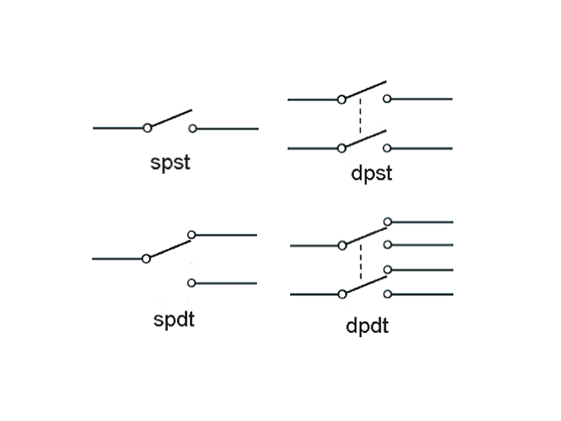
Before going any further, you have to understand how functions a 3PDT footswitch. The 3PDT stands for "3 poles, double throw". Here is a diagram showing the different possibilities :
SPDT DTDT footswitch schematic
Here, we can see that a simple pole, simple throw (SPST) is equivalent to a simple on-off switch; simple pole dual throw (SPDT): equivalent to a toggle switch. So basically, double throw just means that you have two positions for the switch.
A dual pole, simple throw (DPST) is equivalent to 2 SPST, DPDT: equivalent to 2 SPDT.  

From that we can easily conclude that a 3PDT is equivalent to 3 double throws at the same time. You have two position for 3 switches with 2 positions each:
 3PDT footswitch wiring
That means to say that on one position, the middle pins are connected to the ones of the top (2 is connected to 1 for instance), and in another position to the ones on the bottom of the switch.


How to use it for true bypass?

When you want to do a true bypass, you want a simple thing:
  • in one position (position 1), input and output jacks are directly connected, the signal does not goes through the circuit (bypass)
  • Position 2: input jack goes to the input of the circuit, the output of the circuit is connected to the output jack, and a beautiful shiny LED is on.
For position 2, there are 3 conditions to be filled, that is why we need a 3PDT !


True bypass wiring 
With this type of wiring, we have the two following positions: 
True bypass wiring
That is to say on and off for the guitar pedal!


If you do not want to bother to solder directly on the 3PDT (you have to be precise and it is not very practical if you want to modify it afterwards, and most of the times it does not look so good), you can directly use a small PCB to make your true bypass like a boss. You can either make it yourself (model here and here), or buy it (very cheap here).


If you liked this article, thank me by liking the facebook page!
Any questions? Suggestions? Post a comment!

Cheap resistor is cheap !

I needed to get myself a stock of resistors of different values.

It can be very useful when you want to try different values or when you forgot to order THE resistor that you absolutely needed!

cheap resistors

I got this 1280 metal film 1% resistors pack on Amazon. There are plenty of offers of the same kind, it is directly imported from China, and resistors are perfectly fine.

I measured some of them and did not notice any significant difference with the theoretical value.

For me, it is really a good deal and a good start if you want to constitute a stock of components at a reasonable price! Of course, it is still a good idea to buy some small packs of the most used values like 1k for instance.