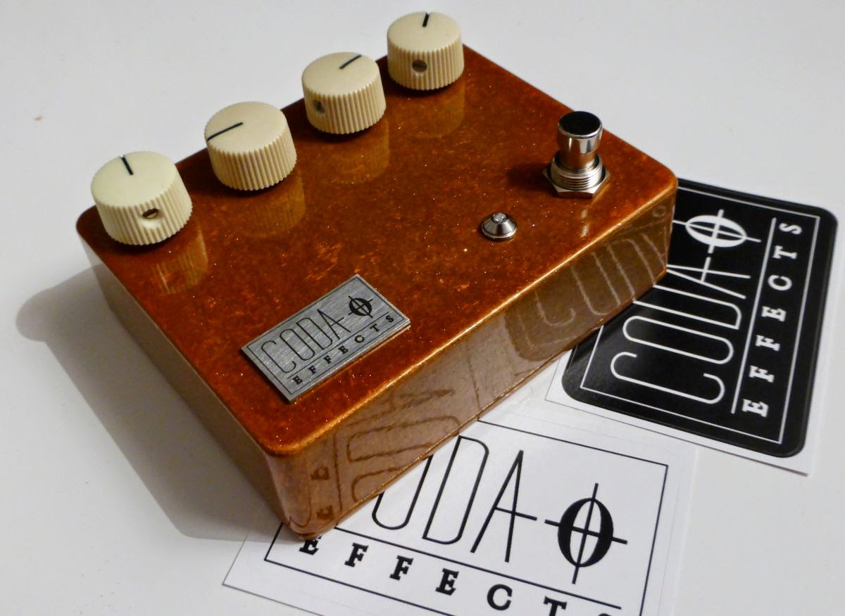
Here is the Big muff Ram's Head clone I have made recently. The Ram's Head is one of the most iconic Big muff models. Produced in 1973, it was the second issued version of the Big Muff, just after the Triangle model. Multiple versions of the Ram's Head existed until 1977, including the "violet era" Ram's Head that sells around 1000 dollars on ebay! The Ram's Head v2 is well known as it was used by Pink Floyd's guitarist, David Gilmour. He used the Big Muff combined with a boost in order to have a nearly infinite sustain during some solos, like the famous Comfortably Numb's one.
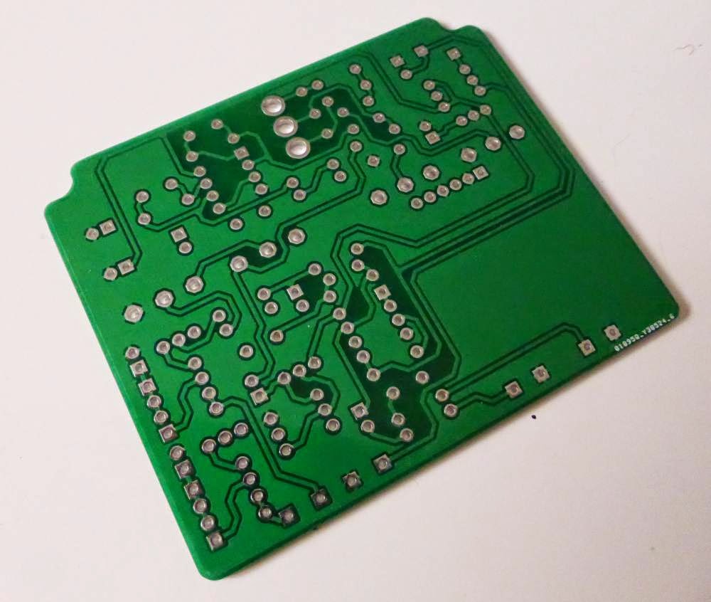
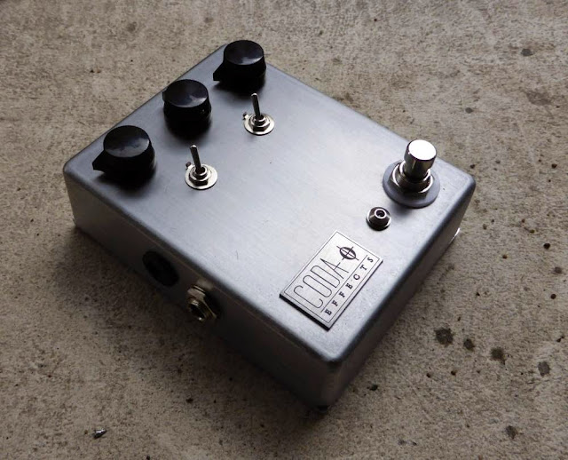 I decided to make this version, with a PCB from musikding. I am currently prototyping a double sided PCB to use it in 1590B enclosures. Here, the PCB is single layer, so I had to use a 1590BB enclosure. I polished the enclosure with sandpaper 140, then 400 and 800 to have a thin polish, following the same direction to make it look like brushed aluminium. I washed it with acetone, and add 2 layers of satin varnish to avoid corrosion.
 I followed the classic scheme of a 73' Ram's Head Big Muff (Gilmour!). I used Wima MKP2 capacitors and one electrolytic to stabilize the power supply. I added two switches to control the amount of mids (switch 1) and bass/trebles (switch 2). The first switch allows you to change the 4,7nF capacitor of the tone stack for a 10nF, thus increasing mids. The other switch plays on the resistor and capacitor at the entry of the circuit, giving us 2 options: a very bassy / smooth one which is the classical ram's head, perfect for doom or stoner rock, and another more trebly, gritty and scratchy!
 With the PCB, it was quite easy to organize the wires inside the enclosure. With a BB sized enclosure, there is a lot of room!

Technically the Big Muff is not a fuzz but a distortion with most of the saturation coming from diodes. However, it has 2 distortion stages, causing the heavily compressed and saturated sound of the Big Muff. The sound is finally close to a fuzz. Lets have a look on the circuit schematic:
I know, it seems horrible and over complicated... Too many components! But lets divide it in 5 sections:
 The first section (input section) is simply a buffer to adapt the impedance of the guitar to the first distortion stage, and which amplify also the signal. As OP amp did not exist at that time (1973, remember?), this is made with a transistor wired in common emitter. Today, a simple OP-amp would be enough! First, there is an input resistor which will diminish a bit the amplitude of the signal. Then, a coupling capacitor will remove any parasitic DC current that mights come from the guitar. Changing the values of the coupling capacitor and input resistor can changes the amount of bass and trebles of the big muff. That is how I made the switch on the pedal. A bigger value resistor and a higher capacitance for the coupling capacitor will increase the bass response of the unit. Then, a transistor wired in common emitter will amplify the signal. Depending on the amplification of this stage, the saturation will be more or less important. The amplification is set by the different resistors on this circuit. Changing resistor's values can increase or decrease the overall gain of the unit. Next, there is a coupling capacitor (again), and a potentiometer wired as a variable resistor that will allow the user to set the amplification on this stage = gain of the Big muff!
 The second and third part (first and second clipping second) are in fact exactly the same circuit. It is used to distort the signal, through the clipping induced by diodes. There is first a coupling capacitor (if you look carefully there is one at each section's start except the tonestack), followed by a resistor. Then, there is a transistor wired in common emitter like in the first part of the circuit with resistors to define its gain. A 470pf capacitor will allow more or less trebles to go through the section. Changing the three 470pF capacitors for a larger value (like 560pF) will diminish the trebles of the unit. This is the case in many clones, like in the Iron Bell from Mojo Hand FX for instance. The diodes will clip the signal and generate the saturation. In classical Big Muff, silicon diodes are used, but in some "boutique" clones, germanium diodes clip the signal (pharaoh fuzz for instance). With germanium diodes, there is less volume, and the sound is even more compressed and saturated! For more infos about diode clipping, read my article about the Jan Ray circuit.
 The third part of the circuit is for me the most important part, the tonestack! This little circuit is what gives the characteristic sound of the Big Muff, and the medium loss, the enemy of guitarist playing in a band. Indeed, when you loose mediums, you litteraly disappear from the mix, as if the guitar was muted! A lot of mods do exist to avoid that: a switch which modify the values of the resistor linked to the ground or the 4,7nF capacitor (which I did on this Big Muff), or to use a potentiometer instead of a resistor, and modify the values of the components to have flat mids, to have a proper medium knob (AMZ tone stack). It is also possible to replace the tone stack by another one, like on the Pete Cornish G2. You will loose the Big Muff style distorsion for a much classical overdriven sound. You can even remove it! You will then have an "in your face" sound with a lot of mediums. You can find this system on the Dwarcraft Eau Claire Thunder for instance. Experiment by yourself, the tone stack is a simple circuit and changes a lot the sound of the Big Muff. A lot of fun!
 Finally, in the output / volume section, the signal is amplified again (to prevent volume loss due to the diodes clipping). It uses a transistor wired in common emitter biased to have a strong amplification. A coupling capacitor is present, followed by a potentiometer wired as a variable resistor to modulate the output signal amplitude. We can recognize (again !) the volume control of a fuzz face!
I really advise you to make a muff once. It is really fun to make and to mod. After reading the Big Muff page, you will know exactly what to change to make it sound like you always wanted!
To go further:
Big muff Page: THE website about big muffs! All the versions, schematics and more! A must read for muff lovers.
Big muff pi circuit analysis (electrosmash): precise analyse of the circuit
AMZ tone stack: study about the big muff tonestack, alternative tone stacks
Big muff mods and tweaks: Some easy mods for your big muff. They are easy but funny mods!


How does it sound?
I did not have time to records samples of this pedal. You will have to believe me then! However, no surprise with this one, it sounds like... a Big Muff! Heavy, oversaturated, compressed, ideal to generate walls of saturation. Ideal for stoner, I played it during almost one hour, playing some Kyuss, Fu Manchu, Queen of the Stone Age whereas I just wanted to test it quickly! The tone potentiometer is really efficient and allows you to go from a bassy heavy sound to something more gritty and aggressive. The bass switch is also really efficient, on one side you have a classic ram's head with a lot of bottom end, quite smooth in the highs, and something more gritty on the trebles on the other side of the switch. The mid switch is also quite efficient, we can hear that sound is more "full" when switched on, and it really works well in a band situation. I am really happy with the result, it is exactly what I was expecting!How does it work?
The Big muff is one the favourite circuit of guitar pedal builders (with the Tubescreamer). Indeed, its circuit is really well known, there is a lot of information available all around the internet, and it is really easy and fun to modify! Each component plays a particular role, and changing it for a different value will change the overall sound of the pedal without damaging the circuit most of the time. It is one of the most cloned guitar pedal, by DIYers or by boutique companies: Mojo Hand FX, Earthquaker Devices, Pete Cornish... Almost every brand has its version of the big muff!
Attack of the clones: all the pedals in this picture are Big Muffs
or "heavily inspired" by the Big Muff pedal
or "heavily inspired" by the Big Muff pedal
Technically the Big Muff is not a fuzz but a distortion with most of the saturation coming from diodes. However, it has 2 distortion stages, causing the heavily compressed and saturated sound of the Big Muff. The sound is finally close to a fuzz. Lets have a look on the circuit schematic:
I know, it seems horrible and over complicated... Too many components! But lets divide it in 5 sections:


I really advise you to make a muff once. It is really fun to make and to mod. After reading the Big Muff page, you will know exactly what to change to make it sound like you always wanted!
To go further:
Big muff Page: THE website about big muffs! All the versions, schematics and more! A must read for muff lovers.
Big muff pi circuit analysis (electrosmash): precise analyse of the circuit
AMZ tone stack: study about the big muff tonestack, alternative tone stacks
Big muff mods and tweaks: Some easy mods for your big muff. They are easy but funny mods!


