Showing posts with label Tips. Show all posts

What tools do you need to make DIY guitar pedals?

When I decided to make my own DIY guitar effects, I was totally lost about the tools that I needed: what do I need to build guitar effects? How much does a good soldering iron cost? And what is a good soldering iron? Where can I buy all that?

In this post, I will try to answer all these questions that we ask ourselves when starting. Lets focus on tools! 🛠️

Electronics bench
(My bench. It is almost never that clean haha!)


ESSENTIAL tools to make DIY guitar pedals

1. Soldering Iron

Lets start with the most obvious tool that you will need: the soldering iron! It is really important to have a GOOD soldering iron when you start. It will really make huge differences when it comes to soldering. 👍

Soldering can be a pain if your soldering iron is not powerful enough: pins of 3PDT, lugs of jack inputs... all necessitate quite a high amount of heat to solder properly. This is why I recommend an at least 30W soldering iron. A high quality iron will also have a more resistant tip, which make it longer lasting.

 Beware! Use a pointy tip soldering iron, and not an electrician soldering iron.

 Beware! I put links to amazon US, so the electrical tools will have a 110-120V plug!

You can also look for second hand tools, there are sometimes very good deal, especially for soldering stations.
  • Basic soldering iron: a classic soldering iron with a pointy end, with a 30W power minimum. It should work quite well! If you just want to make a few pedals, or if you do not want to spend a lot of money, it is an ideal first companion! Here is an example at $14. Of course, you can also buy this kind of soldering iron pretty much everywhere. Just make sure that it has a pointy end, and a 30W power minimum.

 What about adjustable temperature? Adjustable temperature is a nice add on, but not a must. If you work with a small soldering tip, heat will transfer badly, making it more difficult to melt solder. Increasing temperature can be useful in these case. Being too hot can also damage heat sensitive components.

I usually recommend 250°C / 400° Fahrenheit for general soldering. You can increase to 350°C / 650° Fahrenheit for heavy soldering and SMD with a very fine tip.

  • Mid-range soldering iron: you want to make quite a few pedals, or you directly want to invest into quality tools? Weller is a reference in the professional soldering world, and their "professional series" is really, really good. By chance, Weller is really cheap in the US (compared to France), so get one! Here is an amazing soldering iron at $45. It is a professional tool that will last forever. No adjustable temperature though.

  • Professional soldering station: you want to assemble hundreds of pedals? In that case, investing in a soldering station can be a good idea. I found in love with the amazing Hakko FX888D station. Do not be scared by the "toy" look of the station! For only $99, you get a real professional-grade soldering station. No wonder why so many professional guitar pedal builders use one! You can read my review here. 


2. Solder

Before, solder was containing lead. It was used because the solder melted easily at low temperature, and was really practical for electronics as you do not want to heat components too much. However lead has been banned for ecological reason and is now forbidden in the EU (with the RoHS norm). 🌳

You can still find lead solder online. Your choice!
  • Silver or tin? Some people will tell you that silver solders are better. Practically speaking, I did not noticed that much differences when soldering, or for durability. Even in theory, the difference of resistivity is really, really low! Personally, I think it is a waste of money. Moreover, silver can oxidize...
  • Diameter? I recommend a diameter inferior to 1 mm. If it is bigger than that, it will be difficult to be precise enough with PCBs for instance. If you plan on soldering SMD, you can sure go for 0.6mm.
  • So, what to choose? Usually, I buy mine in a local shop (for mojo points maybe?), but you can find it pretty everywhere. I just saw that lead is still legal in the US, so it is up to you! Here are two nice example: with lead or lead-free solder.
Do not hesitate to buy large amounts. There is not a worst feeling than to be out of solder when you want to make a pedal! 😆


3. Pliers, wire strippers, screwdriver and wire cutting snips

Having wire cutting snips is absolutely necessary to cut wires, component legs. A wire stripper is also really useful to snip wires. No need for amazing technological stuff, you can find these really basic tools everywhere. I bought mine in a local DIY shop, but you can find everything online if you want to. Here is a simple pair of pliers to cut wires and leads.

Here are two examples of wire strippers:


A "needle nose" pair of pliers can be really useful to tighten bolts of the different parts we use: potentiometers, jacks, 3PDT switches...etc.

Finally, you will need a screwdriver for tightening enclosures, setting trimpots...etc A multitool like this one can work.


4. A drill

To fit your circuits in an enclosure, you will have to drill holes! A drill is thus absolutely necessary. Fortunately for us, aluminum is rather a soft metal, really easy to drill, so you will not need a crazy expensive drill.

However, as a drill can be really useful in your daily life, you can also choose to buy a good model that will last and will be used for other things than guitar pedal making 🔨

For drilling guitar pedal enclosures, a drill press is simply awesome. However, you might not want such an industrial equipment in your living room like me 😅

Here are some example of drills you can use:
  • The cheap one: I used (and still use...) a really cheap Chinese drill, which cost me around 12 euros (I do not know how is this even possible!), that I bought in a local store. You will surely find other options like this online or in your local DIY shop. Surprisingly, it works really well, and I have no problem with drilling aluminum.
  • The expensive / long lasting option: in this case, try to buy a good drill like a Makita. A professional grade drill is a bit more expensive, but will last forever.
  • A drill press. As I said before, drill presses are awesome for drilling guitar pedals enclosures. What you need is something with a decent amount of power, at least 350W / 1/2 HP. Variable speed or laser lightnings are a nice touch, but not necessary. An emergency stop button is however a must for me. Here is a good price for value one that will fit your orange enclosures very well 😀 Again, check for second hand! Many small businesses sell their old equipment online and you can find some really, really good deals there.
  • Drill bits: I would suggest buying a small number of HSS twist drills for metal drilling, of a few different diameters. A HSS step drill is also really useful. It will allow you drill any diameter you need for the part you are using

 Beware! Safety and drills. Never wear gloves with a rotating machine, remove rings and jewellery (especially your watch) to avoid being dragged in the machine. Don't use your hands to hold the enclosure, use a clamp. Close the safety cover with a drill press. Remember: accidents happen!

Safety tip: keep the emergency number close to your drill.

There it is! You have got all you need for guitar pedal making! If you take really basic stuff each time, it can cost you around 70$ only! Lets now see "non necessary but helpful" tools that you might need from times to times.


Optional tools for guitar pedal making

Everything listed here is not absolutely essential, but can be really useful. In order to make clear what was really helpful and what was not, I rated each tool on the "nice but not essential" scale. 5 is the max score (essential), 0 the worst (completely useless).

1. Tweezers (usefulness: 4/5)

I hesitated to put these in the "essential" section. If you want to hold a component while soldering (and not burn yourself), to bend or maintain a wire precisely, having tweezers is tremendously useful.

Here is a nice set of electrostatic tweezers. Electrostatic is a plus if you use them for SMD soldering for instance.


2. A third hand (usefulness 2/5)

What is a third hand? It is a simple tool with two arms, which allows you to hold parts. Most of the time, there is also a magnifying glass. It can be useful to hold a part while soldering, like a potentiometer, so your left hand is free to hold solder for instance. It can be useful to tin wires also.

To be honest, the magnifying glass is useless, even for SMD. But it makes the third hand look a bit like a helping little fellow, which is nice. I use it from times to times, but not a lot.


3. A desoldering tool (usefulness 4/5)

It is very likely that you are going to make mistakes from times to times, as every human being does. The problem with electronics is that soldering is really easy. However, desoldering can really be difficult, especially if you do not have the good tools... There are 2 cheap tools that will help you (a bit...) to desolder stuff:
  • Desoldering braid: this is what I use when it comes to desoldering. You heat it above the solder you want to remove, and once hot, it will absorb the solder. The downside of this system is that it heats up a lot, and you can burn a bit the PCB, or damage the component you are trying to remove... But it is very cheap, which is nice, and it works!
  • Desoldering pump: another useful tool to desolder. I never used it actually, but I plan on buying one because it seems easier to use than desoldering braid. It is a kind of syringe that will absorb melted solder. A simple one like that can do the job. If you are willing to invest a bit, try this amazing pump. It is crazy efficient with the silicon tip and works really, really well!


4. Combination wrench (usefulness 4/5)

Tightening pots, jacks and 3PDT switches with flat pliers can be really annoying on the long run. Especially if you make quite a lot of guitar pedals.
In that case, I would recommend to buy a combination wrench set. With it, you can tight all the mechanical parts of your pedal easily and fast. I use it every time and never regretted the investment!

Here is a nice set of combination wrench. You can find cheaper ones, but low quality tools are really a pain and can be damaged easily. If you are in Europe, Facom is THE brand for such tools, with a life guarantee included. Expensive but you get what you paid for!

Some prefer socket wrench. I think they have a tendency to scratch enclosures so I prefer combo wrench. You can find cheap multitools that will do the job with socket wrench though, wo do as you please!


5. Round file (usefulness 3/5)

Some holes that we need to make while making guitar pedals are quite huge, especially for the power jack. A round file can help to drill these kind of holes, as well as non standard diameters required for LED bezels for instance.


There it is!
That is all I use to make my guitar effects, and it is really sufficient! See? You do not need a lot... If you clone one "boutique" pedal, you should have spare enough money to buy most of it!

Was this post useful? Join the Coda Effects community by liking the Coda Effects Facebook page. You can also follow Coda Effects on Instagram.


To go further:
Nice video from MAKE about electronics tools. Fun to watch!
Geofex guide about starting building effects.

Tutoriel: how to prototype with a breadboard

Prototyping is not always an easy task with guitar pedals. One solution is to heavily mod an existing pedal. But what if you want to start from scratch? How to test things before designing a circuit and solder everything?

Well, we have a simple solution for that: using a breadboard!
DIY guitar effect breadboard

Let's go! In this blog post, we'll see why the breadboard is such a cool tool and how you can use it to design and test your own circuits.


Make your own DIY power supply: yay or nay?

Let's be honest: buying a power supply is not the funniest thing ever.

It is quite expensive (and I have to admit that I would have prefered to add another fuzz that I do not need a nice pedal to my pedalboard than a power supply! 😁) and differences between the several models on the market is not very obvious...

So I asked myself: is it possible to make a DIY power supply?

Power Supply Carl Martin Pro Power

In this blog post, I will explain how a power supply work, what are the good criterias to choose one from an electronics point of view and if it is a good idea to make one yourself. Let's go!

Why I publish my circuits schematics (and why you should do the same!)

When I made my first commercially available pedals, I chose to publish the circuit schematic online. Transparency always has been a missing thing in the guitar pedal marketing world, so it was a very natural move for me.

However, when I spoke about it with friends or colleagues, they all said to me: "why would you do this? You undermine your business by publishing everything!"
Coda Effects Dolmen Fuzz


So here are my answers about why I think being transparent is a must when making guitar pedals, and why I think you should do the same if you build guitar pedals.

The different types of diodes

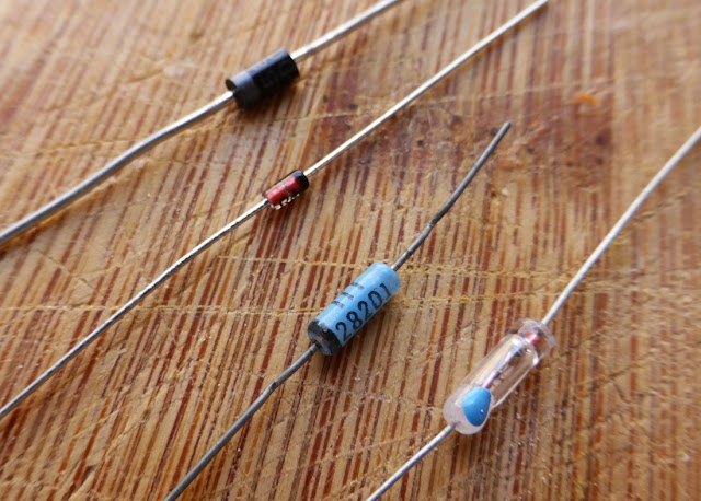
There is a very common marketing point that we see all the time with "boutique" guitar pedals: the famous vintage ultra-rare licorn-made type of diodes! Germanium diodes are often associated with a vintage and warm tone, whereas silicium diode sound harsher and fuzzier...
diode types

Time for a blog post about it!

What is a diode? How do they work? Which one should I use when making guitar effects?

Best capacitors for guitar pedals: which one to choose?

I like to say that electronics are like Legos.

If you step on it, it hurts! Just kidding, it seriously works like Legos as well! 😃

You have to choose different bricks (the electronic components: resistors, capacitors, diodes, IC...) and to assemble all of them following a schematic.

The only problem is: like there are different colors for the lego bricks, electronic components are declined in various versions, with the same value.

For instance, many many different capacitors can be found with the same capacitance value: Panasonic SMF, Wima MKP2, FKP2, MKT standard... What a mess! Lets try to make order in all of this, and to see which capacitors are best suited for our use (guitar pedals).


The 6 elements of capacitors

There are globally 6 main types of capacitors: electrolytic, ceramic, film, tantalum, polystyrene and silver-mica capacitors.

The type of the capacitor is simply a description of what it is made of. 

You should also look up for the capacitor working voltage (more on that in a bit). The tolerance of a capacitor is the maximum difference between a capacitor theoritical value and its real value. You should always look for that too; some capacitors can have tolerance values as huge as 40%!

The smaller the tolerance, the better. 😊

Here are a few examples of through-hole capacitors. From left to right: 150pF ceramic capacitor, 1uF tantalum capacitor, 10nF Panasonic SMF film capacitor, 10uF Panasonic FC electrolytic capacitor and a 0.33uF Wima MKP2 film capacitor.

type of capacitors guitar pedals

Lets start:
  • Electrolytic capacitors: they are cylindric. They usually have high capacitance value, so I would advise to use this kind of capacitors for any value above 1uF.
    They also are polarised most of the time, so beware with the orientation. A good model which I use a lot is the Panasonic FC serie: top quality and a nice black and gold look! 
  • Ceramic capacitors: they are used for small capacitance value, around 10-500pF. They are not very appreciated by audiophiles, because they do not let pass some bass frequencies: they work as a high pass filter at 100Hz.
    If you make your guitar signal goes through this kind of capacitor without any alternate solution (another capacitor in parallel for instance), you will loose bass. However, when placed at strategic points of the circuit, they are very practical to choose how many trebles you want to go through. Usually, they have a high tolerance, so I recommand to look after models with a low tolerance.
  • Film-mica capacitors: they are used for low values like pF like ceramics. They are better than the ceramics, however, they are much bigger and more expensive. I would advise you to stay with the ceramics and save money!
  • Tantalum capacitors: drop-shaped capacitors, used for values around uF. They are not very good for audio, and quite expensive. The only advantage compared to other capacitors of the same values (electrolytics, film caps) is the space saving. Sometimes, their defects in audio can be useful to create a harsh sound good for some kind of dirty fuzz like big muff (for instance, the black arts toneworks pharaoh fuzz uses tantalum capacitors)
 My 2 cents about tantalum capacitors:
Tantalum capacitors are great because they are so small, so they are use in many electronics devices like your phone or computer. However, they are many ethical problems with coltan (the mineral used to make tantalum) mining, with human rights violations. More infos here. I try not to use tantalum caps because of that.
  • Film capacitors: our favorites! Their value is in a large range from nF to 1 uF. You will use this kind of capacitors a lot! Moreover, most of them are really good for audio applications: MKP2 from Wima are a reference in the audio world. Panasonic SMF ECQ are also great, and have an easier-to-work-with shape with long lugs. Finallys, MKT standards are also quite good, and cheaper.

Here is a table to know which capacitor to use:
Value Capacitor type Examples
10-1000pF Ceramic, Silver-Mica Vishay ceramic caps, military grade ones are nice too
1nF-1uF Film Wima MKP2, MKS2, Panasonic SMF
1uF and more Electrolytic Panasonic FC
Except when indicated of course.


What about the working voltage?

The working voltage is the maximum voltage a capacitor can accept.

If you go above this voltage, your capacitor can be damaged! It is thus very important to use a tolerance which fits our usage.

In guitar pedal, we rarely use a voltage above 18V. So any capacitor with a tolerance above 18V is good.

Generally speaking, the bigger the tolerance value, the better.

 Beware! With bigger working voltage also comes a bigger capacitor size. Electrolytic capacitors in particular can be HUGE! So always check the capacitor size as well.


    Examples of capacitors in commercial pedals

    Lets review a few pedals that some of you migh already have on your pedalboard! I will show you the guts of a few commercial pedals, and you will see what kind of capacitors they use.


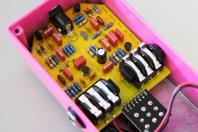
    Mojo Hand Iron Bell (Big Muff inspired fuzz):

    Iron Bell gutshot

    Here, we can find ceramic capacitors (small yellowish ones) and Wima capacitors that are film capacitors as well (red squares). There are also Panasonic SMF (dark red capacitors). Very good capacitors overall! No surprises from this very good brand.


    Fulltone OCD (overdrive / distortion)

    Fulltone OCD components

    Here, we can see lots of ceramic capacitors (blue "drops" everywhere on the circuit, and brownish round caps), and 2 electrolytic capacitors (black cylinders on the top of the circuit).


    Bearfoot Pale Green compressor

    Bearfoot pale green inside components

    Finally, in this Bearfoot pedal, we can see one tantalum capacitor (orange drop on the left of the circuit), MKT capacitors, probably Epcos brand (blue boxes), electrolytic capacitors of different sizes (small and big black and white cylinders). Good stuff here too!


    If you liked this article, thank me by liking the Coda Effects facebook page! You can also follow Coda Effects on Instagram.
    Any questions? Suggestions? Post a comment!


    To go further

    How to build your first DIY guitar pedal (step by step tutorial)

    You have never made a guitar pedal before? You are a bit lost and do not know where to start?

    Here is the perfect place! I decided to write a full tutorial for beginners, to build an Earthquaker Device Acapulco Gold, step by step. No excuse not to get started!

    The Acapulco Gold is a simple, yet very fun pedal to play with, and is perfect for beginners. The circuit is simple and easy to mod as well. With this tutorial, you should be able to build your first guitar pedal!

    If everything goes well, you should get a guitar pedal like this in the end:

    Acapulco Gold clone

    Ready to make your first guitar pedal? Let's get started!

    Debugging DIY guitar effects

    Rule #1 in guitar pedal building is: "It NEVER works at the first attempt"

    So you will have to learn quite quickly what to do when one of your wonderful DIY guitar pedal is not functional. Fortunately, beginners or tired experts often make the same very common mistakes.

    Debugging guitar effects

    In this article, I made a small list of things to check when your pedal does not work, from the most common to the least common errors. This is of course not an exhaustive list, but it includes a set of common problems and errors that you will surely encounter one day.

    Here is my small troubleshooting guide.

    Enclosure art: how to make good looking DIY pedals

    One of the nicest parts of making guitar pedals is having a personalized design. However, it is quite hard to make good looking guitar pedals.

    Here are a few techniques to make guitar enclosures pretty! You can of course combine these techniques to get the best looking pedal possible!

    I will present you a lot of techniques, from the most basic ones to the most professional looking ones.


    1. Bare aluminum enclosure

    It is the simplest way to do: just let the enclosure in bare aluminum.

    Please don't do that.
    DIY guitar pedal bare aluminum
    Bare aluminum enclosure guitar pedals simply do not look good. They really look like something cheap and dirty that you have done quickly in your garage, whereas you have probably spent a lot of hours on it!

    It can be nice for prototyping though, you can improve the design later on if you are satisfied with the result. (practically speaking, it is very rare to improve the design... and I like good looking prototypes so not for me!)
      Pros
    • A circuit in a box is better than a circuit without a box... 
    • Cheap
    • Quickest possible method

      Cons
    • Not really good looking
    • Do not really reflect your hard work and dedication

    Relay Bypass: final code

    After the crowdfunding campaign, I decided to update the relay bypass code.

    Indeed, this first version was nice, but one main drawback that was feedbacked to me is that the switch was activated on release, which was not always very intuitive or easy to handle. Moreover, I wanted to add a "temporary" bypass option in the Montagne Tremolo.

    Montange Tremolo Relay Bypass

    In this post, I am going to explain a bit the new code and to show you how I did it.

    If you have not read my post about Relay Bypass, I highly recommend you to read it before reading this post. All the basics of microcontrollers are presented there.

      Tip! The full code is available on Github. With the relayonpress.c and header.h files, you will have everything needed to code or burn chips.

    If you already have a GitHub account, you can Star the project for updates, or Fork it to modify it and make your own Relay Bypass code.

    Lets go!

    Hakko FX888D: a $100 high quality soldering station

    Let's face it: your good old soldering iron is not always the best pal to work with.

    I had some troubles with mine: no support to put it when I busy doing something else than soldering, which can be quite dangerous if it falls or burn something. Moreover, the power cord was quite short and not very flexible, so it was not always easy to find a good "spot" for it in order to be perfectly comfortable. Finally, it takes a long time before getting hot enough to solder, and 30W is sometimes a bit low to solder big potentiometer or jack legs.

    So I decided to invest a bit in a soldering station.

    After reading a lot on the web, I have found this little gem: the Hakko FX888D, a Japanese soldering station that you can find for $96 on Amazon

    Here is mine:
    Hakko FX888D

    14 electronics suppliers for guitar effects (with pros and cons)

    Finding good electronics suppliers is a key issue when building guitar effects professionally. Indeed, they play a huge role in traceability and quality of the components (where the components come from and what they are exactly), and also the price of these components. Sometimes, they can also add delays if they are bad with handling orders and shipping it quickly.

    Goods electronics suppliers are the root cause of a good build quality for a pedal builder.

    With my crowdfunding project, I have an intermediary position. I cannot order directly from manufacturers (because I would have to order thousands of units at least), but I can order from electronics wholesalers!

    Already 95% of the components have been ordered, and I already received quite a lot of parts! Here is a picture of the switches I got this morning (more pictures will follow in a next post):


    Create your own pedal company: good or bad idea?

    If you already have made a few pedals yourself, you surely have thought about selling them or at least build some of them for other people. Create your own guitar pedal brand seems like a good idea on paper, however there are many pitfalls.... Lets talk about it!

    Disclaimer: I make effects myself, and this post is not intended to "kill competitors" (with my 30 pedals a year...)! On the contrary, I think it is way better to be transparent and to talk about it: this is only my opinion, and feel free to express yours in the comments section :)

    It is a complex matter that is not always easy to discuss peacefully because of money, and there are many different opinions on the subject. It is also the source of really long yet exciting threads on DIY forums (check this one!). The simplest option for me is to discuss it from my point of view as a builder. Thus, I will talk about Coda Effects, and well, just once will not hurt, about me, and give you some tips if you want to jump in it!

    Early 2013, I started to show interest in guitar pedal building: after opening a Fuzz Face, I was quite astonished by the simplicity of the circuit (there is almost nothing in there!), and I realized that building guitar effects might be simpler that I thought.

    Fuzz Face inside

    Eagle for making guitar pedals PCB: getting started (part 1/3)

    Sometimes, especially with complicated builds with a lot of components, or when you have to build several times the same pedal, it is easier to use a printed circuit board (PCB) than veroboard or turrets board. A PCB is easier to assemble, and it prevents from doing many mistakes that can occur when using veroboard: false contacts, misplaced component, complicated wiring involving a lot of wires...etc.

    "Eagle" is the name of a beautiful animal, but it also stands for "Easily Applicable Graphical Layout Editor", the name of a famous software that helps you to conceive and make printed circuit boards (PCB). I already used it a lot to make PCBs. For instance, I made a few Klon buffer boards with it. I decided to write a serie of articles explaining how to use it to make PCB for your guitar pedals.

    Article parts:
    • Getting started (you are reading this one now)
    • Tracing the circuit (to be published)
    •  Creating the PCB layout (to be published)

    Eagle 
    Become free to make PCB like you want with Eagle


    Why using Eagle?

    There are many different different software to create PCBs that are available nowadays: DipTrace, KiCad (open source), Express PCB, Fritzing... Why using Eagle instead of these ones?
    Well, there are several reasons.

    Eagle is free. If you are using Eagle for your personnal use, it is a freeware. Of course, there are limitations that come with the freeware version, but they are not really a problem when it comes to guitar pedal PCB development: maximum size of 100 x 80 mm (4 x 3.2 inches), which is really big for a guitar pedal PCB, only 2 layers maximum (well, we are not going to use more anyway), and one schematic maximum per project. If you want to sell your projects, you will have to buy it, but for simple projects like guitar pedals, the Lite edition is enough and costs only 69$! If you need to buy it, respect the developpers, do not be ill-eagle (badum tsss) and buy it.

    Eagle is well documented. There are a lot of books, websites, videos that are dedicated to Eagle software. If you ever encounter a problem, or if you do not know how to use a precise function, you will always find a solution somewhere. I will write a list of useful websites down this post.

    Eagle has the most complete libraries. When creating a PCB, you need to specify what component you are going to use in your circuit. Is it a small 1/8W resistor, a big 1W one?  Is it an electrolytic capacitor or a tantalum one? You can imagine that it is very important to precise it in order to have the good component "shape" on your PCB. In order to do that, you have lists of components that are called "libraries", which contains hundreds of different components! Eagle has a lot of libraries for all kinds of components, and some libraries had been made especially for guitar pedals!

    Eagle is easy to use. Most PCB softwares are easy to use, and Eagle is too! The "graphical" word in "EaGle" simply means that you have a wysiwyg interface. The interface is easy to use, and let you directly move the components on the board. Last thing, it works on windows and mac, which is nice if you are using different operating systems.

    Convinced? Let's get started!


    Installing Eagle

    Download Eagle on CadSoft website, and install it as a freeware (except if you are going to sell the PCBs you make with it)


    The libraries

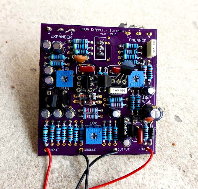
    When you create a PCB, you need to be very precise about which component you are going to use. Indeed, if you put a wrong reference somewhere, the spaces between the lugs can be too short / too long, the component could be too big to fit the PCB...etc. For instance on this PCB:
    Superfuzz PCB circuit board
    You can see that every component fits perfectly its location on the PCB. This is because when conceiving the PCB, I used the correct references for each components.

    A library is simply a list of components referencing components sizes, values and shapes. Eagle comes with already a lot of libraries pre-installed. Some of them will be really useful (Resistors, Capacitors, Inducors (RLC), transistors, supply...etc), some of them not (Zilog microprocessor devices?).

    Some libraries had been created specially for guitar pedal PCB making:
    Gauss Markov library: very easy to use library with a lot of useful components.
    Madbean pedals library: Brian (owner of madbean pedals) made available libraries for making guitar pedal PCB.
    I strongly suggest that you download these libraries. They are easy to use, and contains all the basic tools that you need for making guitar pedal PCBs.

    To install a library, unzip the files, and copy the .lbr files in the "Eagle v7.2/lbr" folder. It is in the applications folder on mac, or in the program files folder on windows.

    Then, open Eagle. You should have a window like this, which is the control pannel:
    eagle control pannel
    You can see that there is a "Libraries" folder that can be expended. It contains all the libraries that you have in the "lbr" folder, including the ones you just downloaded and copied.
    To tell Eagle which libraries you are going to use, you need to expand the "Libraries" folder, click right on the library you want to use and click on "Use".
    Eagle how to use librairies
    You can see that you have a quick description of the library on the right. It can help you sometimes to choose whether you want to use a library or not.

    Ok so the big question is now... Which libraries should we use? Either you can use every library, but you can easily get lost with the number of different components available, and redundancy of some components. In my experience, I only use a few libraries compared to what Eagle is offering... Guitar pedal making is quite simple electronics, and does not require a lot of differente components.
    Here are the libraries that I use when making a PCB:
    • Gauss Markov libraries (all libraries)
    • Madbean libraries (all libraries)
    • belton-engineering.lbr (if you are using tubes)
    • con-jack.lbr (if you want to implement DC jack on your PCB)
    • diode.lbr
    • ic-package.lbr
    • led.lbr (you will only use LED3MM or LED5MM (classic 3 or 5 mm LED) or DUOLED if you want dual colored LED)
    • linear.lbr (IC, OP amps)
    • pot.lbr (potentiometers, nothing else you stoner!)
    • rcl.lbr (dream library with all resistors, capacitors, inductors)
    • regulators.lbr (voltage regulators)
    • supply1.lbr and supply2.lbr (mainly for the ground symbol)
    • switch.lbr
    • transistor-fet.lbr, transistor-neu-to92.lbr, transistor-npn.lbr, transistor-pnp.lbr, transistor-power.lbr, transistor-small-signal.lbr, transistor.lbr (you should have almost every transistor now!)
    • v-reg.lbr (voltage regulators)
    OK! That is already a lot of components, and should be largely enough for any guitar pedal circuit! And if a component you absolutely need is missing from these library, do not forget that you can use other libraries, or download libraries online!

    Now we are ready to start!
    First we have to trace the schematic... in the next blog post!

    If you have any question, do not hesitate to post a comment!
    Was this article helpful? Subscribe to the mailing list or like the Coda Effects Facebook Page to know when next part will be published!

      Relay bypass with anti pop system: noiseless and clickless true bypass

      Did you like my post about relay bypass? At least I did, and now I use it in almost all my pedals! Thus, they are longer lasting, and we avoid the mechanical noises of a 3PDT. However, I noticed something annoying: the relay bypass makes more "pop" noises than the 3PDT, especially with high gain circuits...

      Indeed, relays tend to switch from one state to another much quicker than big mechanical 3PDT switches, which causes the "pop" noises to appear. The gainier the pedal, the more it will amplify the pop and make it louder.

      So I adapted a system that I have found on Stompville that suppresses all these noises. Here is the result, with a (very) simple "before and after" video:


      Ultimate guide to guitar effect wiring: how to wire DIY guitar pedals properly?

      Your guitar pedal circuit is finally populated and ready to rock! However, you still have to solder all the wires... I noticed that it was during this step that beginners encounter most of the issues that go along with guitar effects making.

      Especially with veroboard, you can quickly get a huge mess of wires going everywhere in the enclosure, with the so-called "spaghetti wiring" that we all achieved at least once when starting to make guitar effects!


      Why you should NOT paint your guitar pedal enclosures yourself

      I know this is a bit against the concept of DIY, but the more I am spray painting enclosures, the more I notice that the results are not as great as a commercialy available prepainted enclosures.

      First, sanding the enclosure is a long and painful task and is mandatory if you want a clean surface to paint on. Avoid the long long hours spent carefully polishing your enclosure !

      Then, a lot of thin layers are required if you want a proper painting, and most of the time, the painting will still be fragile and sensitives to shocks. I got craks or scratches on the paint really quickly... Nice if you want a beaten-up, vintage, relic look, but not if you want something really clean and durable. You will end up having something similar to the first tall font russian big muff that had paint quality issue:

      Big muff tall font low quality paint

      Black Arts Toneworks Pharaoh Fuzz clone

      I want to make  Big Muff variants using my Coda Effects Big Muff PCB, and show you how to make them yourself. Lets start with the boutique version of the Big Muff that made it popular again on the stoner / doom scene: the Pharaoh Fuzz! Produced by Black Arts Toneworks since 2011, it was an immediate success because of the huge, warm, doomy sounds it can produce.

      Here is my version:
      Pharaoh Big Muff clone
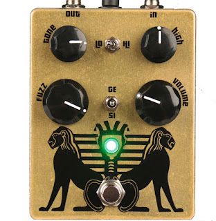
      As you can see, the Pharaoh has more controls than a classical Big Muff. There are the classic gain / volume / tone controls, like a classical Big Muff, plus a few other options. Here is the original version of the Pharaoh:
      Black Arts Toneworks Pharaoh Fuzz
      There are a "high" potentiometer that allows us to set the amount of trebles, and two switches. The first switch is a 'high / low' switch, that allow us to have 2 types of gain settings for the pedal: low gain and high gain. It modulates also a bit the trebles. Finally, you can choose the type of diodes in the last distorsion stage with the second switch: classic silicon diodes, no diodes or germanium diodes!
      Black Arts Toneworks Pharaoh Fuzz clone
      Finally, there are some modifications on the circuit. For instance, input and output capacitors are 10uF tantalum capacitors, which will let a looooot of bass go through the circuit!

      Here is a gutshot (yes, I had fun drawing this!):
       Black Arts Toneworks Pharaoh Fuzz clone
      You can see the tantalum capacitors that are drop-shaped. I try to avoid as much as possible to use it in my guitar pedals. They are not especially good for audio, expensive, and most of all there are not really "ethical friendly". Tantalum is produced from coltan, a mineral that is the root cause of many conflicts, especially in Congo. Illegal mines were opened without any regulation, degrading environment in an uncontrolled way, with many Human right issues (a bit of reading about that on wikipedia). Traceability is a big problem with electronics. Most of the time we do not know how, where or in what ecological context components are made... For tantalum capacitors, just know that they are easily replaceable by electrolytic capacitors.

      Wima capacitors are much better for that: they are made in Germany (and thus, their production must respect European ecological laws and regulations). This is why I try to use them as much as possible:
       Pharaoh Fuzz clone
      So, how can we make the Pharaoh from a classical Big Muff PCB?

      Here is the schematic from the Big Muff page:
      Pharaoh Fuzz schematic
      As you can see, it is very similar to the Big Muff circuit! We can use the Coda Effects PCB and modify it following the above schematic. Here are the modifications to do:
      - no mid knob, 470k for R5.
      - no R2 resistor (we will use a switch instead)
      - no D1/D2 diodes (switch here too)
      - no R8 resistor. (replaced by a "high" potentiometer)
      No big changes!

      If you want, Rullywow sells a PCB especially conceived to make the Pharaoh Fuzz, named "King Tut". If these mods seems a bit difficult to do, you can buy this PCB to make it easier ! Rullywow creates really nice PCB, and this one is no exception, and is of very nice quality.

      First, we will remove the mid knob by placing jumpers on the mid knob pads, like indicated on the build document.

      To include the switches, we will have to use a 125B enclosure, it will not fit in a 1590B. We will have to use long lugs potentiometers to place switches so they do not touch the circuit board and create false contacts.
      For R2 and D1/D2, we will use switches:
      - SPDT on-on for choosing R2
      - SPDT on-off-on to choose D1/D2 diodes.


      Choosing R2: switching between the Hi/Lo setting of the Pharaoh

      We use a "on-on" SPST. Signal arrives to the center of the switch, and goes through a resistor, 39k ("high" setting), or 390k ("low" setting):
      Pharaoh mod
      Try to make the connections on the other side of the PCB, it will be simpler. With this switch, you can choose the R2 value! In "high" position, there will be a lot of gain and trebles, whereas in "low" position, the sound will have more bass, less trebles.

      It can apply to any resistor in the circuit, so feel free to experiment! Of course, some resistors are more interesting than others... I let you try!


      Diodes choosing: 3 positions switch

      We will use the same system for the diode switch. We are going to use a 3 positions on-off-on SPDT switch in order to have: germanium diodes (3 to have assymetric clipping), no diodes or classic silicium diodes. The second set of diodes to replace is D1/D2:
      There it is! We have our two switches. Beware of false contacts with these switches: try to reduce the length of naked cables.Voilà ! On a déjà nos deux switchs !


      Treble potentiometer

      Last mod to add to have exactly a circuit like the original design: the treble potentiometer. In fact, you just have to replace R8 (tonestack resistor) by a 25k potentiometer. Just connect the lug 1 and 2 to each pad of the R8 resistor:
      Pharaoh mod
      It can also apply to any resistor! You can investigate to find your favorite resistor to modulate ;)
      There it is! Voilà! We have got our Pharaoh Fuzz PCB!

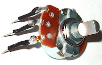
      You can solder the other potentiometers now.  Beware: if we use "classic PCB-mount" potentiometer, the switches will not fit in the enclosure (they will touch the PCB and create false contacts). We will have to use "long lug" potentiometers like this ones:
      long lugs potentiometer
      You can also use classic potentiometer and make the lugs longer with soldered wire with solid copper wire or cur resistors / diodes lugs for instance.
      long lugs potentiometer solder

      You can now drill the 125B enclosure, and rock! :)
      Have fun!

      To go further:
      Official Pharaoh webpage : if you are interested in buying the original pedal
      Veroboard version of the pharaoh: a bit annoying and complex to make, but doable!
      King Tut PCB: dedicated PCB conceived by Rullywow

      Relay Bypass: conception and relay bypass code

      You might already have heard about "relay bypass", or even used it without knowing it. It a different true-bypass system than the classical 3PDT switch. Instead of using a mechanical 3PDT switch, a soft switch, a microcontroller and a relay are combined to turn the effect on and off.

      Relay bypass PCB DIY

       So... Why bother? My 3PDT switch is great, don't you think?

      As you may already know, 3PDT switches are the main cause of guitar pedal failure. These switches are not particulary though, and they often break, especially as we smash it continuously with our feet on stage.

      A classical high quality 3PDT switch is rated for 30,000 activation cycles. With relay bypass, we use a relay that will play the mechanical role of connecting ins and outs. Relays are usually rated between 10 and 100 millions cycles! Thus, this system is much more reliable.

      Moreover, the soft switch that we use to activate the guitar pedals also last longer than a 3PDT, usually around 50,000 cycles! They are also easier to replace, as there are only 2 connections to make with the relay bypass system, and not the full 3PDT wiring.

      This blog post will present you how does it work, and how to make your own relay bypass system using a microcontroller, from the beginning to the end! Long stuff (but good stuff?)!

      Guitar effects and reliability: 5 things to improve to make your pedals longer lasting

      I am building effects since three years, and now that it has been a while, I noticed first failures on my devices. In this article I am going to describe what are the main causes of guitar effects failures that I noticed or that people report to me, how to repair it, and how to build your pedal to make them long term lasting or easily repairable.
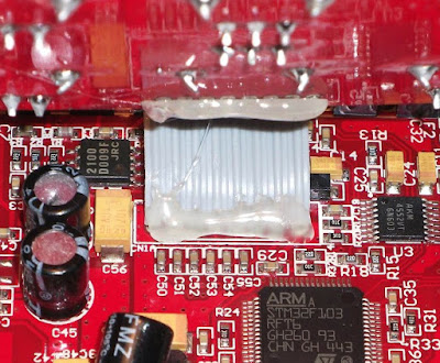
      Oxydated chip guitar pedal


      1. 3PDT switches

      3PDT switches are the main reason why a pedal stops working. A broken 3PDT switch can cut your sound, and the pedal is not easy to switch on and off. 3PDT (and switches in general) are mechanical devices that suffer when activated a lot of times. Usually, good quality switches are rated for 30 000 cycles, but with the way we treat our pedal (kicking them all the time on stage), they usually fail sooner than that. Moreover, most of the times, we do not use good quality switches, but rather “China Blue” 3PDT that are not that reliable (but way much cheaper than Alpha switches).

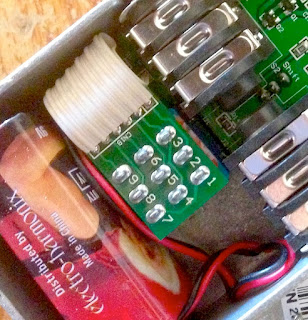
      Replacing a switch is easy but sometimes quite annoying, as you have to rewire everything. To make replacement easier, you can use 3PDT miniboards and ribbon cables. This system is used in many commercial pedals, like in Electro Harmonix or even Diamond pedals:
      3PDT board electro harmonix PCB

      But what if you just want something more reliable? Another solution is to use relays instead of 3PDT as a mechanical system to switch the signal. A normally open momentary soft switch can be used with a microcontroller to drive a relay to switch the signal. Indeed, relays are rated for way more cycles than mechanical 3PDT. For instance a Panasonic TQ2-L 5V, which is a classical relay is rated to last between 10 and 100 million cycles! The momentary switch is really easier to replace than the 3PDT switch, only 2 cables to solder. Here is an example from the Dr Scientist Bitquest pedal (great brand!):
       Relay Bypass guitar pedal
      I am planning on using this kind of system on my pedals soon. I have written a code for a PIC 12F675 microcontroller to use this kind of system. I am now designing a PCB to use it as a standard activation system, with some tricks. Also, this switching scheme is totally silent, which is nice!


      2. Wiring dessoldering

      When wiring the pedal, cables are not always really fixed, and the solder can break and cause a disconnection in your wiring. This can happen quite easily on the 3PDT jack where there is a lot of wiring going on, or even on input jacks. It can make the pedal mute, or generate a huge amount of noise if there are grounding issues arising from a dessoldered wire. It is easy to fix (just ressolder the wire), but quite annoying if the person cannot fix it at home (no soldering iron…etc) and needs to send the pedal over. There are two ways to prevent that. The cheap way to do it is to apply a kind of glue on the soldered wires to avoid physical stresses that cause unsoldering. This is the case in this Caline pedal (Chinese cheap clones):

      Caline Reverb PCB inside
      But the best way to prevent it is to include the wiring directly on the PCB, ie include the jacks and 3PDT on the PCB. It is possible to use a separate PCB for the true bypass wiring like in this JHS pedal:
      JHS True bypass PCB
      Or you can include the switching scheme directly on the PCB. I am planning on including it directly on the PCB on the new pedals I am prototyping. It also makes assembling easier and faster.


      3. Loose jacks and 3PDT

      This is a classical problem. Input jacks and the 3PDT can sometimes become a bit loose, even if you tight them with a pair of pliers. In the worst case scenario, the nut or the bolt can be lost in the process, and the pedal would be quite difficult to use if the input jack or the 3PDT “enters” inside the enclosure… It is really easy to fix, but it is a very common problem, and quite boring to repair because the customer would have to send it over (or I would have to send screws to repair it) just to fix a loose jack. There are two ways to avoid this: either your tight it a lot with a pair of pliers, either you can include jacks directly on the PCB.

      However, it has one downside: if the jack input is not working anymore, it is quite boring to replace because dessoldering and ressoldering of the jack is not easy. So, do not forget to use high quality jacks like Neutrik NMJ6HCD2, and not to overcrowd the PCB around the jacks to make dessoldering possible.

      I am designing my first “commercial” pedal, and I plan to include the jacks directly on the PCB. It avoids a lot of wiring (reason 2), and prevents loose jacks.


      4. False contacts

      If you let your PCB “free” in the enclosure, or just wire it without solid core wire (bendable wire), the circuit board can move in the enclosure. Sometimes, it can create false contacts that are quite boring to fix because you never know where it comes from. Also, it happens a lot with veroboard, where the copper side can make false contact with the bottom of the enclosure. The classical "spaghetti wiring" of beginners is also quite dangerous for that...

      Guitar pedal spaghetti wiring
      My recommendation would be to use PCB mounted potentiometers, which make the PCB fixed in the enclosure. If you are using a veroboard, use solid core wire to make the wiring, so you can bend it and try to fix the veroboard in the enclosure. But my ultimate recommendation would be: do not use veroboard. Honestly, it increases the risk of mistakes (misplacing components on the boards, complex wiring…), and can create false contacts easily. A PCB does not cause all this problems and is much more reliable in terms of assembling. This is why I use mostly PCB in my pedals now.


      5. Component failure

      Actually, I have never seen a component failure per se. Most of the failure I observed resulted from a power supply mistake. The most common case is with MAX1044 (voltage inverter / voltage doubler IC), that can only accept 10V maximum. If someone tries to apply an 18V voltage for instance, the chip simply stops working. Another thing that happens is when someone uses an inverted voltage on a pedal using a normal voltage (polarity inversion). Usually, the diode that protects the pedal from it usually just burn / melt and has to be replaced. Here is an example of a melted diode:
      Burnt diode guitar pedal

      For the MAX1044, I use a socket so it can easily be replaced. For the diodes, I use a “long legs” package on my PCB so I can just cut the legs of it, which makes dessoldering easier. Also, SMD components are much more difficult to replace, so I would advise to avoid it.


      There it is! This are the 5 main points I noticed concerning guitar pedal failure. I am sure that you can spot other things that make your pedal fail, do not hesitate to tell me by posting a comment!
      If you like this article, thank me by liking the Coda Effects facebook page, or by subscribing to the newsletter!